Pico Technology, a leading innovator of PC-based electronic test and measurement equipment, has added four new features to its flagship PicoScope 7 oscilloscope software.
The new features are designed to empower engineers who are debugging, characterizing, and verifying operational reliability of their complex electronic and automotive designs. The latest release of PicoScope 7 T&M Stable includes:
- Rise/Fall time triggering:
Rise and fall time triggering allows users to capture and analyze signals based on their transition times, specifically the time it takes for a signal to change from a certain voltage level to another. It can be set to trigger on a rising or a falling edge. Trigger controls are used to set upper and lower threshold voltages, the transition time and whether to trigger when the signal edge transitions in greater or less than a specified time, or inside or outside a range of times.
The Rise/Fall time trigger function is useful for several purposes, including:
- Signal integrity analysis: rise and fall times are critical parameters when analyzing the integrity of high-speed digital signals. By setting a trigger condition based on the rise or fall time specified in a device datasheet, non-compliant signals can be easily captured and observed.
- EMC/EMI design compliance: high frequency harmonics radiating from fast logic devices can cause an electronic circuit to exceed prescribed EMI limits. Rise/Fall time triggering can be used to validate that those devices have been set up correctly and are consistently operating within specification.
- Drive circuit validation: control systems for valves or motors typically have slew-rate control of the command voltages, as abrupt changes in voltages or currents can cause mechanical damages. The Rise/Fall time trigger function can be used to check for proper operation of those circuits.
For further information: https://www.picotech.com/library/oscilloscopes/rise-fall-time-triggering

- Measurements Logging
PicoScope provides automatic measurement of 24 time-domain and ten frequency-domain parameters. Statistics, calculated over many acquisitions can be used to show average, mean and standard deviation of those parameters for the duration of a test. Statistics provide insight into the repeatability of waveform characteristics, which help to confirm reliability and performance characteristics of an electronic design before committing to production. But taken alone, they do not reveal much about the characteristics of long-term drift or response to changing operational conditions such as supply voltage, temperature etc.
PicoScope 7 now facilitates the logging of automatic oscilloscope measurements directly to a .CSV file on the host computer. This feature enables engineers to test their designs over extended durations and view the impact of variables such as supply voltage range, clock frequency stability, temperature drift and others over time.
With demand increasing for robust design performance, Measurements Logging is a key feature that enables users to characterize and verify reliable of their electronic designs in the field, over a wide range of operational conditions.
https://www.picotech.com/library/oscilloscopes/measurements#log
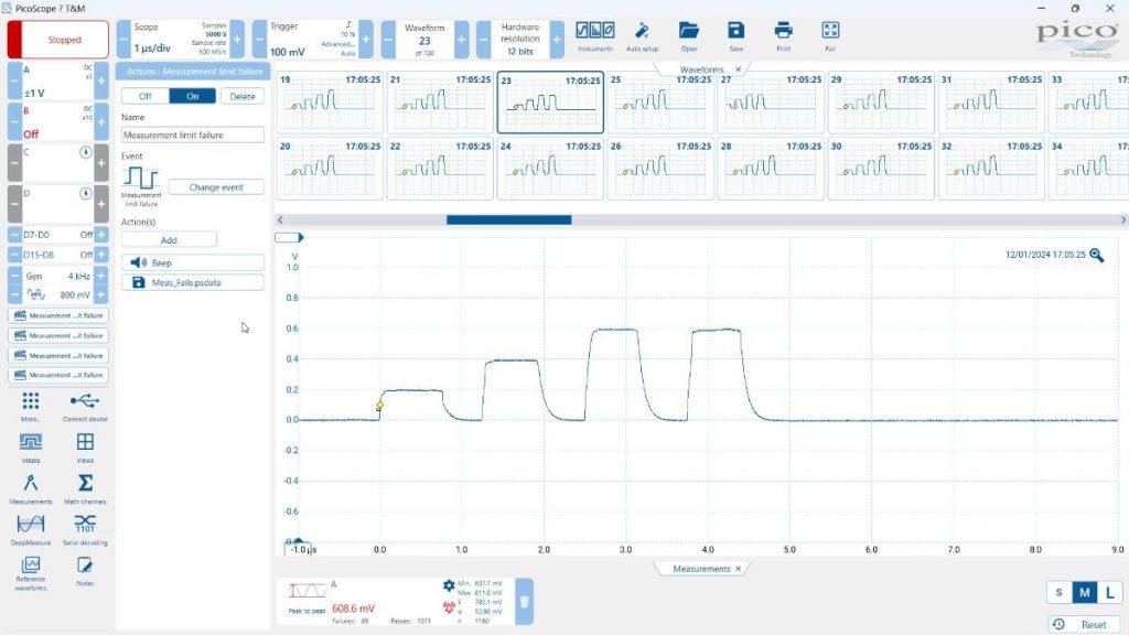
- Measurements Limits & Actions
Measurements Actions build on the standard automated measurements system by enabling the result of any measurement to be automatically tested against an upper or lower measurement limit defined by the user. An Action, also defined by the user, can be programmed to execute on violation of the test. Actions include:
- Beep
- Play Sound
- Stop Capture
- Restart Capture
- Run Executable
- Save Current Buffer
- Save All Buffers
- Trigger the Signal Generator / AWG
Actions enable PicoScope 7 to perform as a semi-automated tool for unattended monitoring of critical parameters during short-medium or long duration tests, either in the laboratory or in the field. At the most basic level, if a measurement test fails, the user can be alerted with a Beep to investigate the cause. Alternatively, a measurement test fail can trigger execution of a file, such as an embedded system debugger, for in-depth analysis of the cause of a problem; effectively using PicoScope as hardware-in-the-loop for system reliability testing.
https://www.picotech.com/library/oscilloscopes/measurements#action

- PSI5 Decoder
Addressing the evolving needs of the automotive industry, PicoScope 7 incorporates a PSI5 decoder, taking the number of serial decoders included as standard to 38. PSI5 is a widely-used protocol in automotive sensor applications, and its addition to the toolset expands the capabilities of engineers working on automotive electronic systems. This enhancement allows for seamless decoding and analysis of PSI5 data, empowering users to optimize sensor performance and reliability.
https://www.picotech.com/library/oscilloscopes/psi5-serial-protocol-decoding
Continuous development of PicoScope 7
“We are thrilled to kick off 2024 off with this major software upgrade,” said Trevor Smith, Product Manager at Pico Technology Ltd. “The new features, including Rise and Fall Time triggering, Automated Measurements Logging and Actions and the PSI5 decoder, reflect our continuing commitment to provide PicoScope users with cutting-edge tools that meet their evolving challenges. It is important to note that that the software also benefits from continuous behind-the-scenes developments to support the latest Windows, Linux and macOS operating systems, processors, and display technologies.”
PicoScope 7 is available to download from https://www.picotech.com/downloads It is free of charge, compatible with all current PicoScope models and many legacy models. Users are encouraged to update their software to enjoy the enhanced capabilities.


