The supply and the wiring harness of a high-power source must be protected against overload conditions and short circuits, as errors such as these of each individual branch could cause a fatal malfunction of the complete system. In order to keep the remaining system functional, each branch should be protected with an individual safety element.
Conventionally a pyro-fuse / melting fuse together with electromechanical relays (EMR) are widely used for the purpose of circuit protection and control in the power distribution unite of the electrical vehicle’s board net. However, due to the higher functional safety and intelligent diagnosis requirement of new electrical/electronic(E/E) architecture, semiconductor-based solutions are drawing attention as its advantages. In the arena of low voltage automotive power distribution, transition from conventional EMR to solid-state relays or smart switches which based on MOSFET technology has been finished. The replacement of automotive high voltage fuses and relays will experience a similar trend, as it enables a safer, more reliable, and flexible protection of HV on-board network system through supper fast turning-off fault application.

Automotive eFuse/eDisconnector application
In electric or hybrid vehicles, an increasing trend toward electrification of auxiliary loads to the high voltage (HV) supply rail can be observed. Malfunction of these auxiliary loads could compromise the availability of the HV board net and functions driven from this supply rail. In order to minimize failure propagation into the vehicle network, the auxiliary loads should be protected with a fuse. In this case the malfunctioning branch can be disconnected individually and all other functions will remain fully operational. As those functions could include safety-relevant systems (e.g., main drive), the disconnect function of the failed branch is a safety-relevant function as well, with a dedicated ASIL rating. For high-availability functions, e.g., DC-DC converter, a redundant approach is typically used. In this case it is key to be able to switch to the backup ECU fast if there is a malfunction in the primary ECU. Such fast transitions and additional features, e.g., activation of the redundant ECU in normal operation, can only be achieved with a solid-state solution.
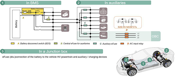
As shown in Figure 2, semiconductor-based fuse can be implemented as centralized (green box-B) and decentralized (cyan box-C) eFuse. A centralized eFuse could be used within the power distribution unit and has higher current capabilities than a decentralized eFuse. In a decentralized eFuse topology, the eFuse could also be part of the auxiliary control unit itself (e.g., DC-DC converter, HVAC compressor, etc.). In both cases the eFuse could re-use the existing infrastructure of the electronic control unit (ECU) e.g., battery main switch, power distribution unit, or on-board charger.
Depending on the individual application requirements, an eDisconnect/eFuse could be implemented as an uni-directional or bi-directional switch. For example a bi-directional relay (orange box-D) for OBC, the MOSFETs in the power stage will be placed in a back-to-back (B2B) configuration (series connection of two MOSFETs with common source). The automotive board net usually consists of the HV battery and one or two battery main switches on high side and/or low side. As shown in yellow box-A of figure 2, the solid-state battery disconnect switch (BDS) replaces fuse, pre-charge, and mechanical contactor with one unit which has power semiconductors in B2B configuration due to bi-directional blocking requirement.

Faster Reaction
The tripping characteristic and short circuit currents of a semiconductor-based fuse compared to a melting fuse are shown in figure 3. In this example, due to the slow reaction time of a melting fuse the maximum short circuit current is ~2 orders of magnitude higher than with an eFuse. Therefore, the eFuse provides not only a faster protection, but also much less fault current need to be conducted by wire harness. This helps to reduce the overshoot and stabilize the board net.

Safer Protection with self-monitoring and diagnosis
The melting fuse is a passive element without any diagnostic functionality. This means that any diagnostic or intelligent functions (e.g., detecting that the fuse has been triggered) must be built externally. An eFuse consisting of power stage and control unit enables monitoring and diagnosis capability. Figure 4 shows an example block diagram of centralized low side eFuse system for auxiliaries.

The system consists of power stage and controller as shown. The power stage has the MOSFETs in parallel with clamping circuit which absorbs inductive energy during the shutting down. Additionally, voltage measurement, current measurement, and temperature measurement are implemented to monitor system statuses (voltage, current and temperature). This information will be processed by µC (reuse ECU of PDU) and circuitry on the controller board to achieve overcurrent detection (OCD), cooling system diagnosis etc.
In addition, an innovative built-in self-test (BIST) for power semiconductor named as SOH (status of health) diagnostic circuitry is implemented on the output stage of gate driver IC. Highly safety relevant application such as eFuse, the integrity and reliability of the power semiconductor is essential, as any failure in the power device could result in a catastrophic and potentially hazardous condition for the end-user. With their excellent manufacturing and high-quality gates, Infineon’s MOSFETs have a very low failure probability. Nevertheless, this reliability is only ensured if the device is operated in the specified operating range. Stress factors which affect the reliability and lifetime of semiconductors include high temperature, fast temperature gradients, overvoltage, and overcurrent. By SOH diagnostic function, one can continuously monitor power device working condition during the lifetime to ensure inside SOA (safety operation area).
More reliable and flexible solid-state solution
A melting-fuse or pyro-fuse is a one-shot device, which means that when it has been triggered, the fuse must be replaced manually. To manually replace the melting fuse, it must be accessible from the outside and maintenance openings must be incorporated into the design. Furthermore, as the trigger of a melting fuse is dependent on the energy required to melt the fusing element, the trigger current is affected by the ambient temperature. The ambient temperature effect is in the range of +/- 10 … 20 percent of the nominal rated trigger current. Another drawback of a conventional melting fuse is the possible mechanical fatigue when the fuse is loaded with pulsed currents. These electrical pulses caused, e.g., by surge currents, start-up currents, inrush currents or transients produce a thermal cycling in the fusing element, which can cause a degradation of the metallic fuse element, in turn reducing the current carrying capabilities [1].
eFuse/eDisconnector and solid-state relays have completely different working principle and switching behaviors which enables a no bounce/pitting and arcing free switching. Therefore, it leads to much less EMI and stress degrading issues. Due to its configurable recovery capability, eFuse is maintenance-free thus no replacement and easy accessibility is required.
The main difference between an eFuse and a load switch or solid-state relay is that: the eFuse is used as a safe disconnecting device and is not designed to switch on capacitive loads. This means that high inrush currents (e.g., due to capacitor charging currents) could cause a tripping of the eFuse, and therefore the turn-on of the eFuse should be done with no- or low-load currents. However, if a PWM control is applied, a solid-state relay (e.g., battery e-disconnect switch) can achieve the active pre-charge function, therefore the conventional pre-charge relay and resistor can be further eliminated.
Infineon’s eFuse Proof of Concept (PoC) [2]
One of the key aspects of the eFuse implementation is the assembly technology. This is the driver for performance and cost of this solution. In the system, space limits the assembly concept options and therefore different implementation variants are available. These boundary conditions include PCB and assembly technology, manufacturability, cooling strategy, cost, as well as isolation coordination.
The heatsink dimensioning and isolation coordination must be considered together in the design. In a typical application the eFuse could be part of another ECU or an individual ECU (e.g., a power distribution unit). Usually for both options, only convection cooling on the housing of the ECU would be feasible. In this case a galvanic isolation of the heatsink must be included in the design. The eFuse PoC is designed for a passive cooling system without any fan or liquid cooling. The power stage has two different cooling concepts, top-side cooling (TSC) and bottom-side cooling (BSC). For more detailed information please refer to Infineon’s application note “Innovative top-side cooled package solution for high-voltage applications“ [3].
Besides power stage PCB, eFuse PoC consists of another two PCBs, as shown in Figure 5. The main PCB (middle) incorporates all the basic functions, such as gate driver, state-of-health (SOH) diagnosis or output stage protection features. The interface PCB (left) is used to control the demonstrator and supports additional switches for controlling dedicated system tests.

Due to the trends of BEV battery voltage rating moving from 400V to 800V+, we have also adapted the initial eFuse PoC to be compatible with different voltage classes by deploying our best-in-class power MOSFET in 600V CoolMOSTM and 1200V CoolSiCTM automotive portfolio. The key product information, parameters, and features of two designs are shown as Figure 6. As SiC MOSFETs have higher maximal junction temperature and better thermal conductivity, the 800V eFuse PoC shows higher current capability compared to 400V design which has Si MOSFETs with same Rdson (3×10mOhm) rating. However, the applied cooling schemes also play a significant role on the system performance, and the specified ratings are indicated values based our reference BSC ang TSC cooling conditions. They are subject to change under customized operating conditions and in the environment of application.

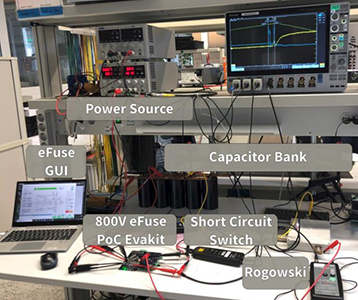
To demonstrate the performance of new adapted 800V eFuse PoC, short circuit test is conducted. The measurement results show the fast reaction and turn-off capability of the eFuse PoC. Due to lab safety regulation constraints, the voltage level of test bench without protection box is limited to 60V. The test setup is designed to emulate the short circuit characteristic without having the battery and auxiliary load.


As shown by figure 7, the power source charges a large capacitor bank which is expected to provide high current pulse during short circuit event period. One so called short circuit switch has exceedingly high current rating is controlled to short the capacitor bank and eFuse PoC kit. The current will arise with high slew-rate (di/dt limited only by wire loop inductance ~4µH), and eFuse PoC kit is expected to react and trip-off as fast as possible when current reaching OCD threshold.
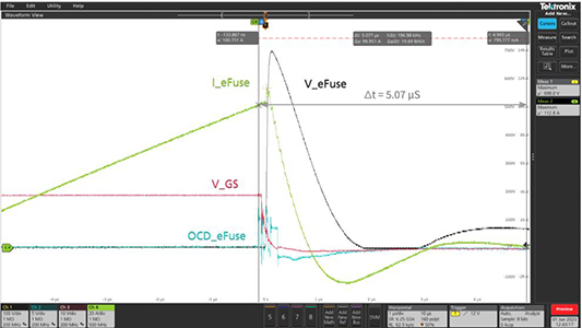
Figure 8 shows the full and zoom view of the short circuit period. The channel 4 ‘I_eFuse’ starts to arise with ~15A/µS when short circuit generated. The channel 2 ‘OCD_eFuse’ has first rising edge when the pregiven overcurrent threshold value 100A is reached. After this time instant, eFuse should start to react to turn-off. Channel 1 ‘V_eFuse’ starts to increase with remarkably high overshoot (Vmax=698V) due to the high di/dt applied on the wire loop inductance during the switching-off transient of MOSFET (channel 3 ‘V_GS’ reaches its threshold value ~5V) and oscillates back to DC-link 60V at the end. Meanwhile channel 4 ‘I_eFuse’ returns to 0A within ~5µS (turn-off time). As the eFuse PoC has implemented clamping RC circuit, the eFuse current and voltage reach steady state after RC clamping circuit finish oscillation.


The main switch MOSFETs are switched off much early when the current turning to decrease. According to the figure 8, from OCD detection (I_eFuse =100.8A) to I_peak=112.7A, it takes only 162 nS due to top-class reaction time of Infineon eFuse implementation. During this period: the gate driver is triggered by OCD to pull down (the channel 3 ‘V_GS’ to its threshold ~5V) and then power MOSFETs are switched off and the eFuse current turns to decline until the energy stored in the cable harness has been consumed by RC snubber.
It is important to notice that even with clamping circuit, eFuse voltage has huge overshoot up to the ~700V as consequence of high di/dt applied on the wire-loop inductance during the switching transient. Therefore, it is very crucial to have accurate estimation of transient peak voltage and inductive energy, as they determine the dimension of clamping circuit (e.g., RC snubber) which protects eFuse transistor away from breakdown condition. Due to higher avalanche capability of the SiC compared to Si device, the RC snubber can be scaled down or eliminated. The SiC MOSFET will go to avalanche mode when overshoot is higher than breakdown voltage. The short circuit inductive energy can be partially or fully dissipated by the power semiconductor devices as their specified avalanche energy. However, it requires a precise analysis of all key parameters (voltage, current, loop inductance, reaction time) of the application environment to estimate the inductive energy. On the other hand, judgement of sufficiency of device(s)’s avalanche energy requires also high-level product expertise as the value is highly test condition dependent. Infineon will support customer to find optimized switch protection schemes (snubber, avalanche, TSV, MOV etc.).
In summary, compared with the conventional melting fuses or pyro-fuse, Infineon’s eFuse PoC demonstrates its super-fast reaction and switching-off capability in a short circuit event. By using our best-in-class CoolMOSTM and CoolSiCTM MOSFET products together with sensing and control circuit, the complete eFuse/eDisconnect is leading to a disruptive innovation of protection measures for the automotive board net electrical applications. Due to the long-term reliability and recovery capability of semiconductor switches, and self-monitoring and smart diagnosis features of ECU, solid-state system fulfills the function safety, intelligent requirement of new E/E architecture of electrical vehicles.
Reference
[1] Littlefuse, Inc: Fuse Characteristics, Terms and Consideration Factors; Application guide; 2014.
[2] Infineon Technologies AG: AN UM_2211_PL52_2212_165057 Automotive high-voltage electronic fuse demonstrator.
[3] Infineon Technologies AG: AN_2101_PL52_2103_112902 Innovative top-side cooled package solution for high-voltage applications.


