As vehicles advance, their electrical and electronic (EE) architectures must keep pace to efficiently handle rising power demands. Traditional distributed and domain-based control systems face growing challenges, including increased complexity, excessive wiring, and communication bottlenecks. Zonal control architecture offers a solution by consolidating electronic control units (ECUs) within localized zones, streamlining power distribution, reducing wiring requirements, and improving system reliability. This article examines the shift toward zonal control, its role in power management, and the key protection strategies needed to ensure safe, efficient operation in next-generation automotive systems.
Smarter, Safer, and More Connected or Efficient, Scalable, and Reliable
Modern EVs integrate advanced capabilities for safety, convenience, and connectivity, driving increased dependence on electronic control units (ECUs). With premium vehicles incorporating more than 150 ECUs, the need for a more efficient and scalable control architecture has become clear.

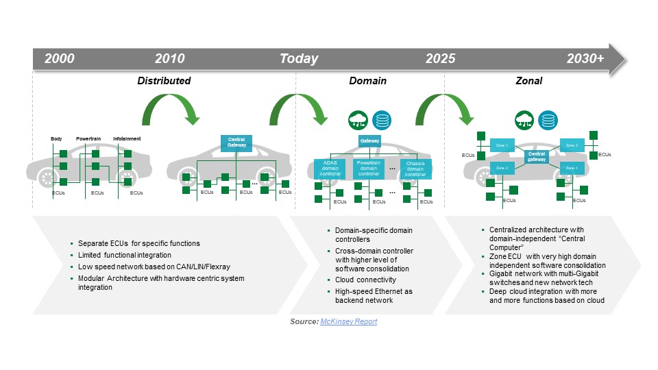
Automotive control systems have evolved from single-layer to multi-layer designs to handle the growing ECU complexity.
- Distributed Architecture: Early designs where each ECU connected directly to a master controller.
- Domain Architecture: Introduced domain controllers to oversee specific functions, easing the burden on the master controller.
- Zonal Architecture: Organizes ECUs by physical areas of the vehicle, with zonal controllers (ZCUs) managing operations within each zone.
Zonal architecture improves safety through faster response times, supports modular scalability, enables high-speed Ethernet communication, and reduces wiring complexity. However, moving from distributed or domain-based systems to a centralized zonal model also requires a redefined approach to distributed power management. Ensuring stable power delivery across zones, while maintaining efficiency and safeguarding against electrical faults, has become a critical design priority.
Boosting EV Efficiency and Reliability Through Zonal Control
Zonal control enhances EV performance by improving battery management, supporting energy recovery, and increasing powertrain efficiency. Zonal Control Units (ZCUs) monitor thermal conditions and sensor data while maintaining reliability in demanding environments that may involve overcurrent, overvoltage, and electrostatic discharge (ESD) risks. Key powertrain elements, including the traction motor inverter and onboard battery charger, are also exposed to these hazards. The following sections highlight protection approaches that improve circuit robustness.
Safeguarding the ZCU
As the central hub within each zone, the ZCU needs to deliver consistent, reliable operation even under harsh conditions. Figure 2 shows a block diagram of the circuits typically found in a ZCU. This article discusses protection techniques for these circuits to ensure durability and safe vehicle operation, along with recommended protective components.
The ZCU requires safeguards against power supply faults, such as overcurrent events caused by supply-side or load-side failures. Protection can be achieved with fast-acting fuses or polymer positive temperature coefficient (PPTC) resettable fuses. Both one-time and resettable AEC-Q200–qualified fuses are available to withstand the rigorous conditions of the automotive environment.
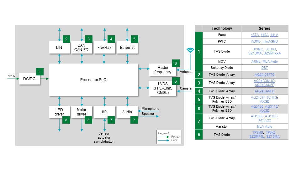
The power supply in a ZCU is vulnerable to high-voltage transients, especially load dumps that generate inductive spikes when power is suddenly interrupted. To protect downstream circuits, a transient voltage suppression (TVS) diode or a metal oxide varistor (MOV) can be used. While MOVs can absorb higher load-dump energies, TVS diodes offer a much faster response and clamp to a lower voltage. Both MOV and TVS diode models are available with AEC qualification.
Equally important is protecting the ZCU’s many communication and control interfaces from damage in the harsh automotive environment. Electrostatic discharge (ESD) and voltage transients pose the greatest risks. ESD diodes and polymer ESD suppressors provide effective protection for both communication and control lines. Low-capacitance devices are preferred to minimize signal distortion and ensure reliable data transfer between the ZCU and the various functions it manages within the zonal control architecture.
Defending the Onboard Battery Charger (OBC)
The Onboard Battery Charger (OBC) (Figure 3) converts AC line voltage into DC to charge the battery pack, typically operating at 400–800 V. As higher-power and faster charging — including 3-phase AC — becomes the norm, each circuit block within the OBC requires protective components, and in some cases, control elements to maximize efficiency.
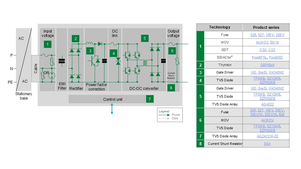
In addition, to common EV transients, the OBC is required to also handle AC power line risks such as overloads and surges. Like any line-powered device, it requires protection against these hazards while also safeguarding communication circuits from data corruption and minimizing internal power losses to help reduce charge time.
Protection Strategies
The first line of defense is a fuse, which provides overload protection. Select fuses with both a high interrupting current rating and a high voltage rating to ensure they will open reliably under worst-case conditions. To guard against surge transients or lightning strikes, a metal oxide varistor (MOV) should be placed as close as possible to the input terminals of the charger. For 3-phase OBCs, additional MOVs can be added for phase-to-phase and phase-to-neutral transient protection.
To further reduce stress on downstream circuits, a bipolar protection thyristor can be used in series with the MOV. The thyristor’s low clamping voltage and high surge current capacity allow the use of an MOV with a lower standoff voltage, thereby lowering the peak transient voltage seen by the charger’s internal circuitry.
For the highest level of safety, a gas discharge tube (GDT) can also be added. A GDT provides strong electrical isolation between the AC lines and the vehicle chassis ground, offering superior protection against fast-rising transients caused by lightning disturbances.
A Residual Current Monitor detects AC/DC leakage or insulation breakdown, with models able to sense DC differentials as low as 6 mA and AC differentials of 10 mA. In the Rectifier Block, thyristors with high current-handling capacity are used to deliver the required power while safely withstanding inrush current transients that pass through the Protection and EMI Filter stages.
The Power Factor Correction Circuit improves efficiency by reducing total AC power consumption. For inductance regulation, pair a gate driver with an insulated gate bipolar transistor (IGBT). Choose drivers with a wide voltage range, strong latch-up immunity, and fast switching speeds to minimize losses. ESD protection is also vital — either through built-in safeguards or external ESD diodes rated for up to 30 kV transients.
The DC/DC Circuit boosts charging voltage and delivers current to the battery. To counter Ldi/dt effects, protect power IGBTs with a TVS diode between the collector and gate. This active clamping method stabilizes the IGBT, and some IGBTs now integrate this feature directly.

The Output Voltage Stage may need protection from current overloads and voltage transients, such as when motors switch on/off or when a cable break interrupts current flow. While some modules include built-in safeguards, additional protection may be required: fuses for short-circuit conditions and MOVs or TVS diodes for transient suppression.
Finally, the Control Unit interfaces with the ZCU. To prevent communication failures or data corruption, apply ESD and transient voltage protection to its I/O lines. The same ESD diodes used for the ZCU CAN bus are suitable here as well.
By combining these protection strategies, engineers can design an OBC that remains reliable and resilient under real-world electrical hazards. Figure 3 illustrates the recommended components.
Guarding the Traction Motor Inverter
The Traction Motor Inverter converts the battery DC to AC current to drive the traction motor. Operation of this circuit block requires safe, efficient, and reliable propulsion. Figure 4 shows the circuit blocks of the Traction Motor Inverter, and the table lists the recommended protection, control, and sensing components.
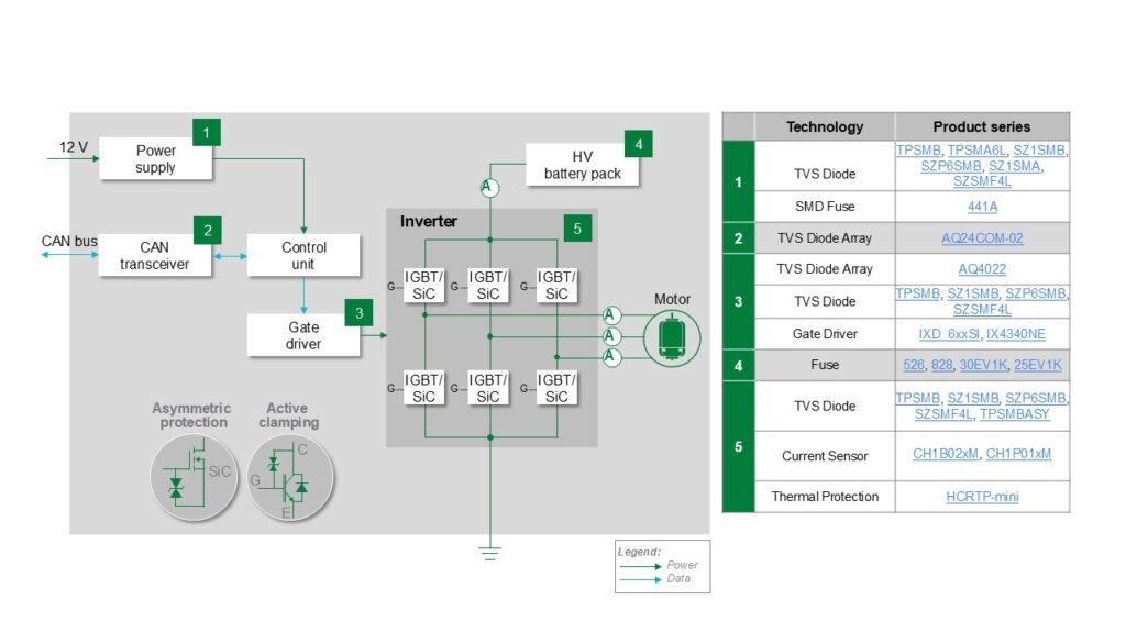
The CAN Transceiver should be protected from ESD strikes using an ESD diode array. The same TVS diode array recommended for the ZCU CAN/CAN FD circuits applies here. The Gate Driver Circuit controls IGBTs or SiC MOSFETs, managing switching to balance efficiency with minimal losses. Protect the driver ICs using ESD diode arrays to absorb electrostatic strikes.
The Inverter Block generates propulsion power. To ensure consistent operation, power transistors are required to be safeguarded against overcurrent, voltage spikes, and overheating. Thermal protectors can disconnect supply current to prevent excessive junction temperatures.
When using SiC MOSFETs, add a TVS diode between the gate and source. For IGBTs, place a TVS diode between the collector and gate to clamp voltage transients, a proven active clamping technique for maintaining device stability.
For motor load monitoring, Hall effect sensors are often used. By detecting magnetic fields around the current-carrying wire, these sensors provide isolated current measurement without adding power loss to the circuit.
Reliable ZCU and Powertrain Operation
As automakers move toward zonal control architectures, ensuring robust operation of ZCUs, onboard chargers, and traction inverters is critical for both safety and efficiency. Integrating proper protection against overcurrent, overvoltage, ESD, and thermal hazards strengthens system durability under demanding automotive conditions. Collaboration with component manufacturers’ application engineers, such as those at Littelfuse, offers additional benefits, from optimized component selection and cost-effective protection strategies to smoother compliance testing and faster certification.