Printed circuit board (PCB) pins are essential components in modern electronic interconnect systems. Although small, they serve an important role in creating dependable electrical connections between individual components and complete circuit board assemblies. PCB pins were developed to allow connector contacts to be mounted directly to a board, reducing the need for bulky standard connectors, loose wiring, or less robust soldered wire terminations.
Individually, PCB pins are precision-formed metal contacts that can be installed one at a time or arranged into organized arrays. This flexibility supports cost-effective and application-specific interconnect solutions, whether connecting components to a single board or linking multiple PCBs within a system. As electronic devices continue to become smaller and more capable, PCB pins have evolved to support higher densities and more compact layouts. They are now available in a wide range of sizes, shapes, materials, and configurations.

How PCB pins are used in electronic systems
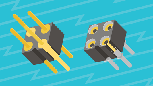
At a basic level, PCB pins are cylindrical male connectors mounted directly onto a circuit board, most commonly using through-hole technology. They may be placed individually or grouped within an insulating housing known as a pin header.
To establish an electrical connection, PCB pins mate with a corresponding receptacle or socket. When engaged, the pin and socket create both electrical continuity and mechanical stability. This allows signals, power, or data to move reliably between components or separate boards within a system.
PCB pin assemblies also offer layout flexibility. Straight and right-angle configurations help designers accommodate space constraints and specific routing requirements in compact assemblies.
They create a straightforward conductive path while supporting multiple connections in compact layouts and adapting easily to different board configurations. When used with mating sockets, they also add mechanical strength to the assembly. With a broad range of available options, PCB pins can be tailored to specific application needs, delivering stable, secure connections with minimal signal loss. Their durable construction withstands shock, vibration, and temperature changes, while low insertion force simplifies assembly and service.
Common types of PCB pins
The continued growth of PCB pin technology has led to several widely used categories:
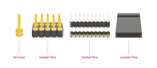
- Terminal Pins – Individual standalone PCB pins
- Header Pins – Male pin arrays integrated into a molded plastic base
- Socket Pins – Receptacle-style contacts designed to accept mating pins
- Jumper Pins – Small connectors used to bridge connections for configuration, testing, or debugging
Each type supports a specific interconnect approach while maintaining a compact footprint.
Typical PCB pin styles
To accommodate different applications and manufacturing methods, PCB pins are available in a variety of styles:
- Single- or Double-Ended – Connect on one side or both sides
- Single- or Dual-Row – Arranged in one or two parallel rows
- Edge-Mount – Installed along and parallel to the edge of a PCB
- Nail Head – Feature a flat-topped head for improved contact or retention
- Solder Cup – Include a concave cavity to hold wire and promote solder flow
- Slotted – Designed with a vertical slot to ease wire insertion and soldering
- Turret – Raised shoulders allow for wire wrap, soldering, or use as test points
- Wire Crimp & Wrap – Square profile pins that enable secure wrapped connections
- Wire Termination (Crimp Terminal) – Hollow pins that accept specific wire sizes without solder
- Shrouded – Include protective features that shield the pin during handling and assembly
- Pogo Pins – Spring-loaded contacts suited for temporary or high-cycle connections. Read Same Sky’s pogo pins article for more details.
This broad range of options allows engineers to match pin selection to electrical performance goals and assembly processes.
PCB pins compared to standard connectors
Board-level design often prioritizes space efficiency and high interconnect density. While traditional connectors serve many applications well, they can consume valuable PCB area and may limit contact count.
For example, common circular connectors and D-sub connectors support a defined number of contacts, typically fewer than the pin counts required by many integrated circuits. PCB pins can be arranged in dense arrays to support dozens or even hundreds of connections within a smaller footprint.
Large board-mounted connectors can also complicate redesigns or upgrades. PCB pins offer greater flexibility in grouping and layout adjustments, which can simplify board revisions and evolving system requirements.
Mounting methods for PCB pins
PCB pins can be attached to a circuit board using several established techniques:
- Press-Fit – Inserted into plated through-holes for secure mechanical retention
- Swaged – Mechanically deformed to lock the pin in place
- Crimped – Secured using controlled compression
- Soldered – Permanently bonded to the board through a solder joint
They are also available in common mounting formats:

- Surface-Mount – Soldered directly to the surface of the PCB
- Through-Hole – Inserted through drilled holes and soldered on the opposite side
- Wire-Mount – Replace bare wire connections using clamps or set screws
- Free-Hanging – Used to connect wires or cables together off the board
The appropriate method depends on mechanical strength requirements, electrical performance needs, and manufacturing processes.
Specifying PCB pins for your application
Selecting the right PCB pin requires evaluating both mechanical and electrical characteristics:
Physical Specifications
- Lead size and pin diameter
- Orientation, including vertical or right-angle
- Mounting hole dimensions
- Compatibility with board thickness
- Pin geometry, such as round, square, or rectangular
- Current and voltage ratings
- Dimensional tolerances
- Required pin density
Contact Materials
- Typically brass, bronze, copper alloys, or nickel-based materials
Plating Options
- Copper, gold, silver, tin, nickel, palladium, or lead finishes, chosen based on conductivity, wear resistance, and corrosion protection
Manufacturing Considerations
- Alignment with insertion techniques and assembly equipment
- Environmental conditions, including vibration, temperature extremes, or corrosive exposure, may also influence material and plating selection
Common applications for PCB pins
PCB pin technology is used across a wide range of industries and electronic systems, including:
- Computers and computing equipment
- Medical devices
- Test and measurement systems
- Telecommunications infrastructure
- Consumer electronics
- Automotive electronics
- Industrial automation
- Aerospace and defense platforms
Their versatility makes them suitable for both high-volume commercial products and specialized, performance-driven applications.
Summary
PCB pin connectors remain a proven and adaptable interconnect solution for modern electronics. They deliver compact, dependable electrical connections while supporting efficient manufacturing and straightforward serviceability. Their widespread use across industries, along with their importance in prototyping and board development, highlights their continued relevance in today’s evolving designs.
For engineers seeking a space-efficient and technically sound approach to board-level interconnection, PCB pins provide a practical and reliable solution. Same Sky offers a range of PCB pins as well as pogo pins for a variety of interconnect needs.