Modern on-vehicle digital video recording systems (DVRs) or OBDs are using accelerometers (g-sensors) to measure on-vehicle acceleration. This allows the DVR to watermark the recording video with date/time/ acceleration information when there are predefined events that occur, such as hard braking or a collision. The watermark is helpful when saving the video to system memory such as a hard disk or SD card. The watermark makes it easy to identify and play back the event video of interest. And the system memory can be saved significantly by keeping watermarked video only and deleting others. However, it is a big challenge to accurately measure acceleration when the vehicle is running due to the combined Earth gravity offset and vehicle vibration on the accelerometer. This article introduces a simple but effective way to solve this problem.

Figure 1 shows an on-vehicle DVR system block diagram. Camera video from the CMOS sensor is taken, processed, and ultimately stored in standalone memory, for example, SD card or a hard disk. As highlighted in blue, an accelerometer, for example an ADXL313, is used to measure vehicle acceleration.
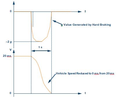
Figure 2 explains how a DVR system with accelerometer works. In the case of a predefined event, for example, hard braking, acceleration is increasing or decreasing significantly as the vehicle’s speed varies. The accelerometer will sense and measure this acceleration which the data MCU/processor can capture and process. Once the acceleration crosses a predefined threshold (for example, –1.5 g), the DVR system will start to watermark the recording video with information such as the date/time/ acceleration value.
In reality, the measured acceleration from the accelerometer is not an accurate reflection of the real vehicle acceleration due to distortion caused by Earth’s gravity offset and vehicle vibration. There are many cases in which Earth’s gravity offset is introduced. For example, when the DVR is installed in the rear view mirror, the mirror’s surface angle with Earth’s gravity is uncertain since the passenger can adjust it by hand. Another example is when the vehicle is traveling on a road that is not 100% horizontal. Also, vibrations from the vehicle’s engine and rugged road conditions are randomly coupled into the acceleration measurement and cause errors.

Table 1 is an examination of how significant error can be introduced by Earth’s gravity offset. The first column is the angle of road slope related to the horizon; the second column is the offset on the g-sensor z-axis that is introduced by Earth’s gravity; and the fourth column is the sensor- measured acceleration on the z-axis. With 1 gof acceleration on a vehicle, the measured acceleration on the z-axis increases with the angle, as the fourth column shows. For example, at an angle of 15° the measured acceleration is about 1.26 gwith 1 greal acceleration on z-axis, so the measured error is about 26%.
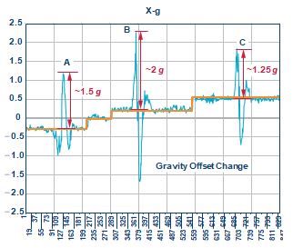
Figure 3. Acceleration output coupled with Earth’s gravity offset and vehicle vibration.
Figure 3 shows a real acceleration event measured with Earth’s gravity offset and vehicle vibration coupled onto the accelerometer. In the diagram the blue line represents acceleration as measured on the accelerometer, and the yellow line depicts the gravity offset introduced by Earth’s gravity. As the diagram shows, there are three peak points observed, points A, B, and C. Point A is about 1.25 g measured, Point B is about 2.25 g measured, and Point C is about 1.75 g measured. By predefining the threshold at 1.5 g, both points B and C are over the threshold, while Point A is below threshold. But, in fact, this result is wrong since gravity offset on the accelerometer is not compensated. As the red color highlighted in the diagram shows, by eliminating the gravity offset effect the real acceleration of Point A is about 1.5 g, Point B is about 2 g, and Point C is about 1.25 g. In this case with the predefined threshold of 1.5 g, Point A and Point B are over the threshold, and Point C is below threshold. This example clearly demonstrates that gravity offset will introduce errors on measured acceleration, which will cause the system to make incorrect decisions. And in reality both gravity offset and vibration are unpredictable, so the error introduced on measurement is also unpredictable. It is quite a challenge to extract real acceleration from the measured data respective of gravity offset and vibration.
However, adaptive reference can adaptively eliminate the error introduced by gravity offset and vibration. It instantly monitors the data from the accelerometer, and any data that exhibits small and slow variation over time is considered to be error introduced by gravity offset and vibration.
This is highlighted by the yellow line in Figure 3. The real acceleration of interest exhibits large and fast variation over time and can be identified and extracted from the measured data by eliminating the error introduced by gravity offset and vibration. This is highlighted as pulses A, B, and C in Figure 3. The basic operation to achieve real acceleration data is described in the following paragraph.
Upon every measurement cycle, the accelerometer measures and stores the data which is used as a reference for the next cycle calculation. At the next measurement cycle, the measured data will be compared to the reference data from the previous cycle, and the results data is compared to a predefined threshold. If the results data is over a predefined threshold, it is identified as a large and fast transit of interest, and will be further processed by system software. If the results data does not exceed the threshold, it is identified as offset and noise introduced by gravity and vibration. The measurement cycle requires a fine tuning algorithm to achieve accurate detection based on different environments. The above process can be expressed with the following formula:
ABS [gn – gn – 1] > gth
Where
gn = g data measured in current measurement cycle
gn – 1 = g reference measured in previous cycle
gth = predefined g threshold
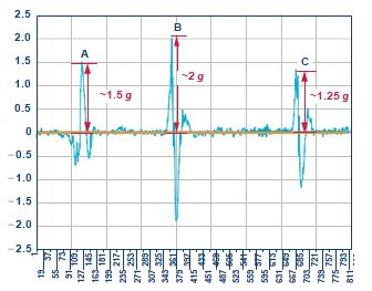
Figure 4. Accurate acceleration after the adaptive reference method is applied.
Figure 4 depicts the calculated real acceleration by eliminating the error introduced by gravity offset and vibration. As shown in the diagram, now the yellow line is close to zero, which means that gravity offset and vibration are almost eliminated. And points A, B, and C are correctly reflecting the real acceleration.
Generally speaking, the adaptive reference method described above should be implemented by software, but in reality it may not be practical to expect the MCU or processor to accomplish it with pure software since the video application is real time and the MCU or processor may lack the resources. As a solution, the ADI ADXL313W accelerometer features ac mode operation and a built-in 32 deep FIFO, which greatly helps in implementing the adaptive reference method to achieve accurate acceleration measurements even with a resource constrained back-end MCU or processor. AC mode operation allows the ADXL313W to keep measured data as the reference used for the next cycle calculation and the built-in 32 FIFO enables the ADXL313W to preserve up to 32 words of measured data, both of these significantly off-load the back-end MCU or processor.

Figure 5. Flow chart to utilize the ADXL313W’s ac mode for accurate acceleration calculation.
Figure 5 is a flow chart of ADXL313W ac mode operation. Once ac mode operation is activated, the ADXL313W will automatically keep the previ- ously measured data as the reference for next cycle comparison against the predefined threshold; if it is over the threshold, an interrupt signal will be active to inform the MCU or processor to deal with it. In the flow chart, delay X ms is set as the interval time between two measurement cycles, and can be fine-tuned subject to the application.
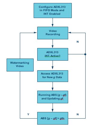
Figure 6. Flow chart to utilize the ADXL313W FIFO for accurate acceleration calculation. Figure 6 is a flow chart of ADXL313W 32 FIFO operation. Once 32 FIFO mode operation is enabled, the ADXL313W will automatically keep up to 32 words of data in the FIFO, and if the FIFO is full, an interrupt signal goes active to inform the MCU or processor accordingly.
Conclusion
The modern vehicle DVR or OBD requires accurate acceleration detection and measurement in order to record watermarked video of interest with a limited memory size. Measurement errors are mainly introduced by Earth’s gravity offset and vehicle vibration, and they are unpredictable, which presents a design challenge to the system designer. The adaptive reference method can be implemented by software to eliminate the error, but this, in reality, may not be practical since DVR or OBD systems can easily be resource constrained. The ADI ADXL313W accelerometer
features both ac mode operation and a 32 deep FIFO, which greatly helps with implementing the adaptive reference method, while significantly off- loading the back-end MCU or processor. Combined with more features such as automotive qualified, high resolution, low noise, and low power, the ADXL313W helps to greatly improve DVR system performance.
About the Author
Ben Wang [ben.wang@analog.com] joined ADI as a field applications engineer in 2009, located in Shenzhen, China. Prior to joining Analog Devices, Ben worked for six years at National Semiconductor. Ben graduated from Hunan University, China.


