
Abstract
This article introduces an accurate series active voltage positioning (AVP) implementation method applied on a μModule® regulator. This method achieves a fast load transient response, minimal board space, and an all ceramic capacitor solution. Compared with a shunt AVP design, this series AVP provides a significantly accurate load line accuracy, which greatly improves the output voltage accuracy. The measured results for the load transient response are presented.
Introduction
Active voltage positioning (AVP), or active droop technology, regulates the power supply output at higher voltage at light load and lower voltage at heavy load. One major benefit of implementing AVP control is to improve the load transient response and reduce output capacitance since AVP allows more room for the power supply to respond to the load transients. A μModule regulator is a complete, tested, and qualified power supply in a package solution. Fast load transient response, minimal board space, and an all ceramic capacitor solution are preferred by μModule regulator telecom and data center applications. However, it is challenging to meet all these requirements with traditional non-AVP control.

This article introduces an accurate series AVP implementation method by adding two resistors to the feedback control loop. The advantage of this series AVP method is that load line accuracy is almost independent of the gm amplifier gain variations, while other AVP implementation methods like the shunt AVP1 would suffer from poor load line accuracy if the gm amplifier gain has large variations. After implementing this series AVP, up to
50% output capacitance could be reduced while peak-to-peak output voltage transient is also slightly improved. Only ceramic capacitors would be needed due to 50% less capacitance, which greatly improves system reliability and cost since the aluminum electrolytic capacitor is much less reliable and higher cost than the ceramic capacitor.

Another benefit to implementing AVP control is to lower the out- put voltage when the load current is large and thereby reduce load power consumption. The LTM4650-2 example shows that the net power savings is 1.4 W or 5.6%, which greatly saves power consumption and extends battery life.
Series AVP Implementation
AVP refers to the regulator output voltage regulated at a point that is dependent on the load current, while with the conventional approach (non-AVP) that voltage is fixed at nominal VOUT for all loads as shown in Figure 1. With the AVP approach, the output voltage drops gradually when the output current is increased. At light load, the output voltage is set to regulate to slightly higher than the nominal value, while at heavy load, the output voltage is set to regulate to slightly lower than the nominal value.1 When load current suddenly increases, the output voltage starts from a level higher than nominal so the output voltage can droop more and stay within the specified voltage range. When load current suddenly decreases, the output voltage starts at a level lower than nominal so the output voltage can have more overshoot and stay within the specified voltage range. The output volt- age should be constrained within the specified voltage limits (between VMAX and VMIN) for all load current ranges.
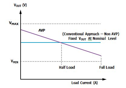
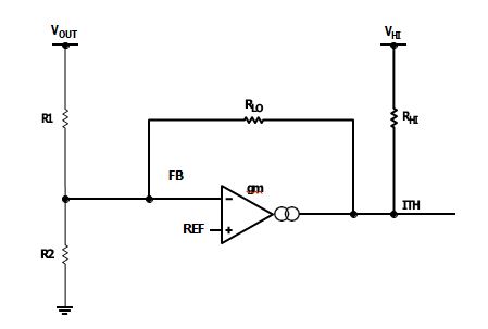
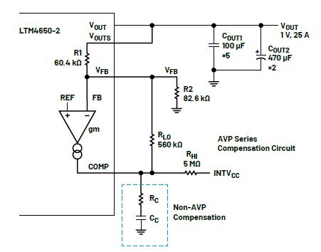
Figure 2 shows the AVP series compensation circuit. The internal reference voltage (VREF) and VOUT feedback are connected to the positive and negative inputs of the error amplifier, respectively. VHI (or INTVCC) connected with RHI supplies the appropriate DC voltage to the amplifier output (ITH or COMP) that keeps the out- put from going into saturation. RLO (feedback resistor) is placed from the output (ITH) to the negative input (or FB). Therefore, RLO dominates the gm amplifier gain. RHI and RLO values should be much higher than R1 and R2.
The load line Equation 1 is shown as:
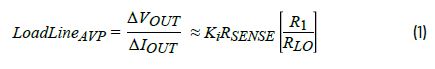
Ki is the current sense gain, and RSENSE is the current sense resistor value (or inductor DCR value for DCR sensing).
Compared with the AVP shunt compensation circuit1, the advantage of the series compensation circuit is that the load line is dependent on R1/RLO gain and almost independent of the tolerance of the error amplifier transconductance (gm). IC processes and designs are vast. Unfortunately, some ICs’ gm values have a part-to-part variation as large as ±30%, plus the shunt compensation circuit AVP has its load line directly proportional to 1/gm gain. As a result, the shunt AVP suffers a poor load line.
AVP Solution on the LTM4650-2 Regulator
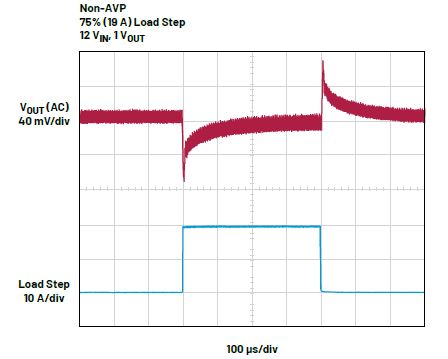
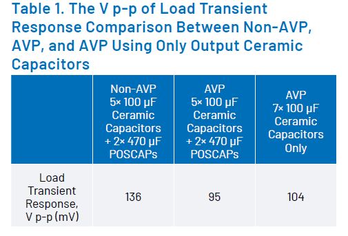
On the LTM4650-2 (current-mode synchronous buck regulator), a nominal 1 V output capable of delivering 25 A load with about ±8% (a 160 mV p-p) transient window. On this conventional regulator (non-AVP), an external RC filtering circuit is required to achieve fast Type II control loop compensation. There is a bank of 5× 100 μF ceramic capacitors + 2× 470 μF POSCAPs on the output side. With a 19 A load step (75% of full load) and a slew rate of 19 A/μs, 136 mV p-p of the transient response was as shown in Figure 3.
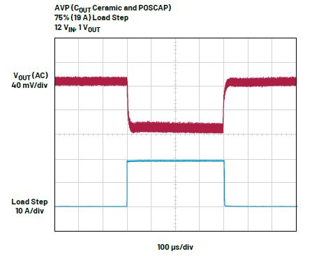
On AVP implementation, an AVP compensation circuit is applied on COMP as shown in Figure 4, but the RC compensation is not required. At the half load (12.5 A), purposefully set the output voltage to a nominal value (1 V) by fine-tuning the R2. On the load transient response, 95 mV p-p of the VOUT was obtained as shown in Figure 5. The transient performance has been improved. With the setting output voltage 1 V at 25 A (full load), the load power is 25 W. By decreasing the output voltage to 0.945 V at 25 A load, the load power is now 23.6 W, and the new savings is 1.4 W for a single output. For the two outputs, the total net savings is 2.8 W.
With the AVP implementation, the two POSCAPs can be replaced by two ceramic capacitors, so a total of 7× 100 μF ceramic capacitors are used on the COUT1. The benefit of using a ceramic capacitor is that it has lower equivalent series resistance (ESR), equivalent series inductance (ESL), cost, smaller size, and more reliable performance. The transient performance has been improved, and the measured result was 104 mV p-p of the VOUT as shown in Figure 6.

Table 1 shows the above measured V p-p of the load transient response of the non-AVP (benchmark), AVP, and AVP using only output ceramic capacitors for comparison.
Conclusion
Implementing the AVP series compensation circuit on the LTM4650-2 μModule regulator achieved an improved transient response performance and lower load-power consumption at high load. Output capacitance of less than 50% is required. Hence, it can replace POSCAPs with ceramic capacitors, reducing cost and minimizing circuit board space. This AVP circuit is also applicable for many other μModule regulators that have an external compensation pin with external RC compensation net- work (for example, LTM4630-1, LTM4626, LTM4636, LTM8055-1,etc.).
Reference
1Robert Sheehan. “Active Voltage Positioning Reduces Output Capacitors.” Linear Technology, 1999.
About the Authors
Sin Keng Lee is a design engineer for power modules in Analog Devices since joining ADI in May 2022. He obtained his B.S. degree and Ph.D degree in antenna, RF, and microwave communications engineering from Northumbria University, UK.
Zhijun (George) Qian is a senior design manager for power modules with Analog Devices. He is responsible for all LTM80xx products and some LTM46xx/LTM47xx products. He obtained his B.S. degree and M.S. degree from Zhejiang University and his Ph.D. degree from University of Central Florida, all in power electronics. He joined ADI in early 2010.