Abstract
Switching DC-DC converters in military applications must meet stringent standards for limits on conducted input noise emissions and typically require input filter networks for compliance. However, when inputs of DC-DC converters are paralleled, noise can combine in indeterminate ways, making filter design difficult. This article discusses the issue and describes a way to achieve a consistent and substantial reduction in emissions using the phased switching frequency synchronization technique.
Article
Isolated and most non-isolated DC-DC conversion is achieved with Switched-Mode Power Supplies (SMPS) for high efficiency, small size, and low weight. A wide range of SMPS circuit topologies can be used, and all generate electrical noise to some extent from transistor and diode conduction transitions. Noise can be radiated, or conducted along input and output lines appearing as differential mode (DM) noise between line and return conductors, or common mode (CM) noise between line and return conductors together and ground.
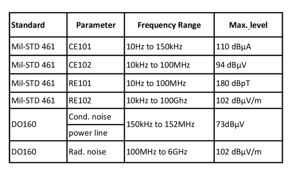
Some noise limits for military-grade DC-DC converters are shown in Table 1. These limits are measured using a standard Line Impedance Stabilisation Network (LISN) set-up (Figure 1), which outputs a signal, normally to a spectrum- or EMI-analyser, which is a measure of the sum of CM and DM voltages across a termination of 50 ohms.
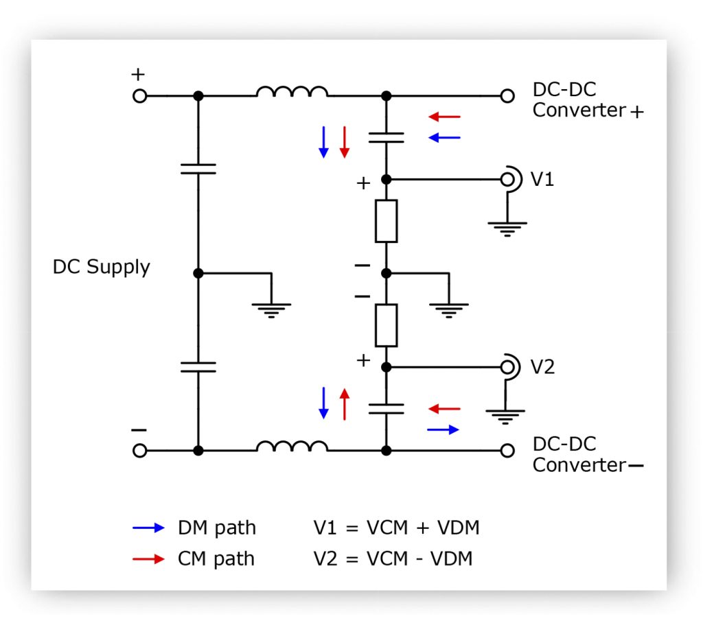
It is clear that to avoid exceeding the EMI limits, both DM and CM noise must be suppressed, particularly as the noise along external connections can swap between the two modes and back again.
Input current waveshape depends on switching topology.
While switching edges contribute to high frequency conducted EMI, the basic operating current waveshape defines the low-frequency DM emissions level, with the highest line response at the switching frequency. Depending on the topology, the operating input current waveshape can be discontinuous, for example, in ‘buck’ derived circuits, or continuous, as in higher power ‘boost’ derived circuits, although these can be discontinuous at low power. In all cases, the current waveform can be closely approximated as the sum of a square wave and a triangle or sawtooth shape repeating at the switching frequency. This is the current into the switching stage of the DC-DC converter. A filter on the converter input, at minimum a capacitor, levels the current to be close to DC with the residual noise required to be lower than the EMI standard limit line.
A way to predict the amplitude of EMI responses is to decompose the current into square, sawtooth and triangular elements in the time domain and apply Fourier analysis to give the amplitude of line responses in the frequency domain. Filters can then be designed from the frequency plot to attenuate the responses to the level required by the EMI standard. For example, a boost converter in discontinuous mode has a triangular-shaped input current waveform with an amplitude I sin(n) at the nth harmonic of:

D is duty cycle and Ip is peak current of the sawtooth.
Depending on the value computed, an input capacitor may be sufficient, forming a single pole giving -20dB/ decade attenuation with frequency. If not, an additional series inductor giving total -40dB/decade, or a C-L-C pi-filter with -60dB/decade could be employed, which could be overall smaller than a single capacitor to achieve the same attenuation. However, a single large capacitor is also likely to have significant Equivalent Series Resistance (ESR) and inductance (ESL), reducing its effect. Adding input filters also introduces self- and parasitic resonances, which can produce ringing, extra EMI responses, and over-voltages, so damping must be considered. This is sometimes achieved with a series capacitor and resistor directly across the converter input. However, often the ESR of the final capacitor in the filter network can be arranged to give a sufficient damping effect. Also, the ‘Middlebrook criteria’ is one constraint that dictates that the output impedance of the filter must be much lower than the input of the following converter for stability. Another consideration for the filter is adequate DC current rating, to avoid excess heating and magnetic saturation at the peak of the current waveform, especially at high temperatures.
Paralleling DC-DC converter inputs
Decomposing current waveforms works to quantify line response amplitudes for one converter, but when two are paralleled, even of the same type, the EMI signature is more difficult to predict. For example, identical converters operating at the same frequency will have a combined noise current I at the switching frequency of:

Where mn is the current amplitude of converter n and ɸn is the switching phase difference between converter 1 and converter n. If all amplitudes were equal at value M, the noise response amplitude I would vary from zero to nM as the converter phase drifts between zero and 360 degrees, causing full or partial cancellation or addition. To minimise noise at the fundamental frequency by cancellation, the converter frequencies can be synchronized and separated in phase with a delay between switching cycle start times of 2π/n where n is the number of converters. Table 2 lists the delays required for up to six converters.
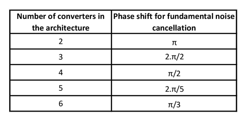
Table 2:Phase shift required for fundamental noise cancellation in synchronized DC-DC converters
Achieving 20dB Attenuation
The required π radians or 180° phase shift for just two converters is just an inversion of the synchronization signal and is easily implemented. Simple logic networks can be designed for other phase shift values or signal timing generated from a microcontroller. Example synchronization waveforms for four converters are shown in Figure 2 with a corresponding EMI plot in Figure 3, comparing responses with and without synchronization, yielding about 20dB improvement. This was measured using four GAIA Converter DC-DCs loaded at 80W total. Complete cancellation is not practically achieved due to component tolerances and small differences in load sharing between the converters. As well as the improvement in conducted EMI level, phasing the converter switching also reduces ripple current in input capacitors. This, in turn lowers capacitor losses and stress and increases overall system reliability.
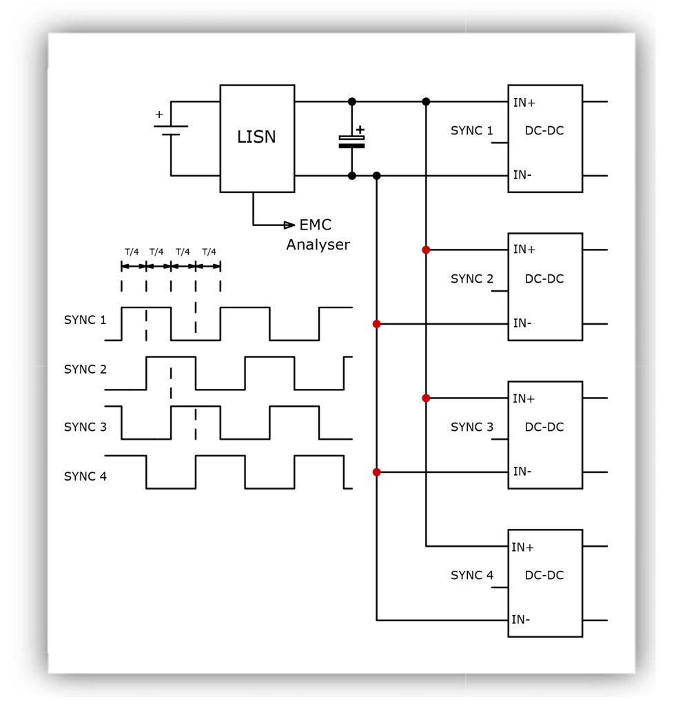
Figure 2: Phased synchronization signals for four DC-DC converters
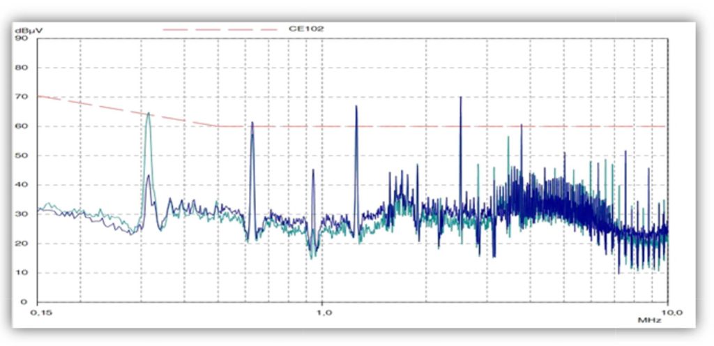
Figure 3: EMI plot comparing synchronized, phased converters (blue) and without (green)
The effect of phased synchronization in the example of Figure 3 is to reduce the 300kHz fundamental response to more than 20dB below the CE102 limit line. However, the higher harmonics are not necessarily attenuated, and some will actually be higher. This is because with four converters and π/2 phase shift, the fourth harmonic, for example, is shifted by a complete cycle, or 2π, resulting in addition rather than cancellation. Higher harmonics will also be more affected by tolerance of the phase shift. However, the fundamental is the most difficult to filter, so cancellation is very useful, while higher harmonics require much smaller inductor and capacitor values for similar attenuation levels.
Noise Attenuation demonstrated in the real world
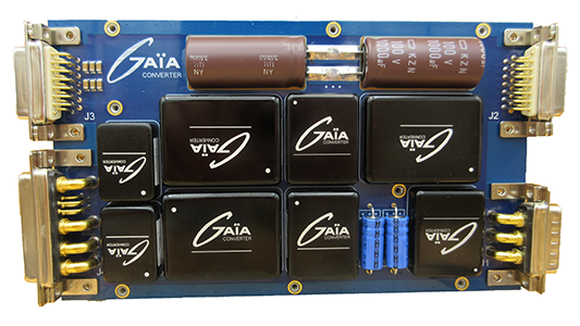
GAIA Converter has demonstrated the effectiveness of the technique of phased synchronization with a board fitted with six military-grade DC-DC converters and a front-end filter/conditioner module. The board provides single and bi-polar outputs totaling 120W from a nominal input of 24/28VDC (Figure 4).
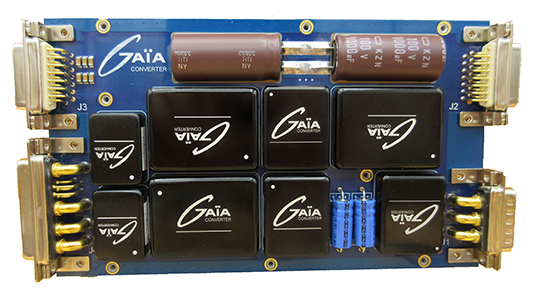
Figure 4: A GAIA Converter demonstrator board with phase-synchronized DC-DC converters
Converters form two separate groups, with control circuitry to perform 180° (π) phase synchronization, with four of the converters grouped and synchronized at π/2. In addition, isolated and non-isolated DC-DC converters are featured, including a point of load converter type MPSGS14ED, which has -36% to +700% voltage trimming, fast output tracking, and a constant current function.
The conditioner module type LHUG150N provides reverse polarity and +/-100V transient protection, inrush current, and power limiting. The module can also enable an efficient 50ms to 200ms hold-up on power interruption, achieved by charging a capacitor to 60V whatever the input and switching it to the DC-DC inputs when the interruption occurs. Because the energy is stored at 60V, a relatively small capacitor can be used. CE102 emissions limits are met with a better than 20dB margin (Figure 5) due to the phased synchronization along with a small 1” x 1.2” on-board EMC filter type FGDS-12-100 which takes up just 5% of the available board area. Military avionics standards MIL-STD-704, DO160, MIL-STD-461 and MIL-STD-1275 are all met.
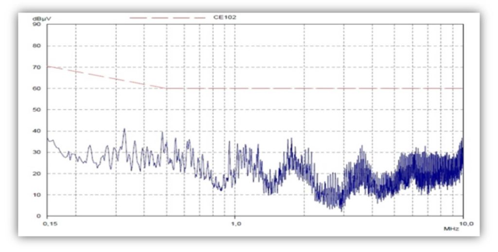
Figure 5: EMI plot from the GAIA Converter reference design showing 20dB margin to the CE102 limit line
Conclusion
The phased synchronization technique with paralleled DC-DC converters makes conducted EMI signatures more predictable, allowing filters to be designed analytically to achieve compliance with EMI standards. Optimal filter designs can then be implemented to significantly reduce their weight, size, and cost, often critical parameters in high-reliability applications such as avionics.


