Abstract
Increasingly, military vehicles are provisioned with electronics for control, communications, navigation and display systems. DC-DC converters provide auxiliary power for these systems but can be subject to high electrical and environmental stress in the application. This article outlines the stress levels defined by the common standards used and identifies the specifications that DC-DC converters need to meet.
Article
Electronics in vehicles has proliferated, to the extent that a modern car has been likened to a wireless-connected data center on wheels. Military vehicles are following the trend with ‘Vetronics’ or vehicle electronics, but with a different emphasis – as in cars, engine control, displays and navigation are needed, but there are additional requirements for communication, weapons control, sensing and data collection, with digital wireless networks connecting to other vehicles and fixed systems. Even AI is increasingly a feature, for situation analysis and autonomous operation, increasing mission effectiveness and reducing risk to personnel. As with passenger cars, high reliability, low weight and cost are also factors for military vehicles.
Vetronics market drivers are the unfortunate recent rise in global conflicts, along with programs to modernize and upgrade vehicles to match competing forces and to take advantage of the increasing capabilities of electronic systems. Analysts Allied Market Research project the value of the global Vetronics market to be $6.5 billion by 2030 up from $4.2 billion in 2020 – a CAGR of 4.67% [1].
The move to electric propulsion in military vehicles is in consideration but typically only as hybrid implementations, with diesel traction engines still the practical option.
Development of new military vehicles is always slow with extensive testing and qualification needed, so existing platforms are often upgraded in parallel. As a consequence, new electronics systems must usually be compatible with legacy associated equipment and an existing in-vehicle power supply and distribution network. At the same time, there is a move to reduce costs using commercial off-the-shelf (COTs) products meeting standard specifications, rather than custom designs, for guaranteed interoperability and interchangeability across different vehicle platforms.
Power rail standards for Vetronics
The nominal battery supply in military vehicles is usually 12V or 24/28VDC and the two main standards in use are UK DEF-STAN 61-5, at issue 7 from March 2020 and the shorter American MIL-STD 1275, at revision F from September 2022. The UK standard covers 12V and 24V systems while the US version is 28V only. The standards describe expected variations in the supply including nominal ranges, spikes, surges and dips, and any connected equipment must withstand these without damage, although in some cases, functionality can be temporarily lost, for example in DEF-STAN 61-5 during dips caused by engine cranking. Immunity to superimposed ripple and reverse polarity connections is also prescribed.
Normal operational supply voltage limits
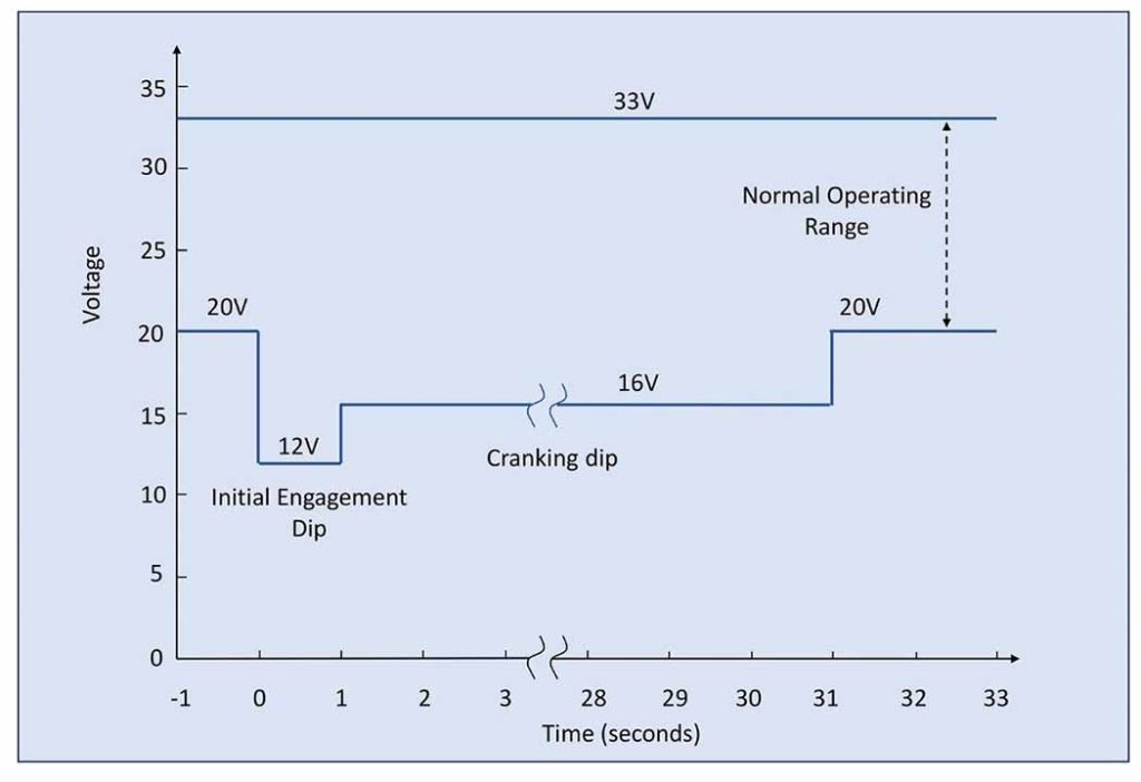
MIL-STD 1275/F defines an operational range of the 28VDC supply with limits of 20V and 33V and with cranking dips to 16V after an initial ‘engagement’ dip to 12V. The levels and timing are shown in Figure 1.

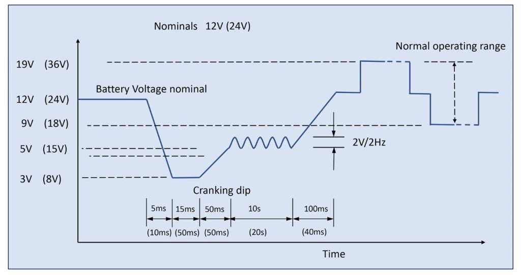
An equivalent graph for DEF-STAN 61-5 is shown in Figure 2 with a normal operating range for 12V nominal of 9-19V, or 18-36V for 12V systems. Note that this is shown as 19-36V elsewhere in the standard, confusingly. The standard specifies the maximum and minimum voltages for 5 minutes, but practically, any connected equipment must withstand this continuously.

End equipment in the vehicles will require a regulated supply typically at some lower voltage, clean from disturbances, so DC-DC converters are used with wide input ranges and fixed outputs. To meet the US standard, the converters should also operate ‘normally and without degradation’ down to 12V for a 28V supply during the cranking ‘initial engagement’ dip. For the UK standard, the value should be 18V with some margin for a 24V supply and 9V for a 12V supply. To cover both standards, a DC-DC converter with a continuous input range of 9-36V would be suitable. Parts such as the MGDM-500 DC-DC converter from Gaia converter [2] are ideal and with their ability to operates down to 8.5V, would also continue to function without interruption during the DEF-STAN 61-5 cranking phase, with even the 50ms 8V level covered by the design margin, though not guaranteed. However, as mentioned, for the UK standard, loss of functionality during cranking is expected (clause B.8.1.1). The isolated MGDM-500 is rated 500W output at fixed 12, 15, 24, 28 or 48VDC and lower power versions are also available in the product range from 4W upwards.
High voltage surges and transients are also present
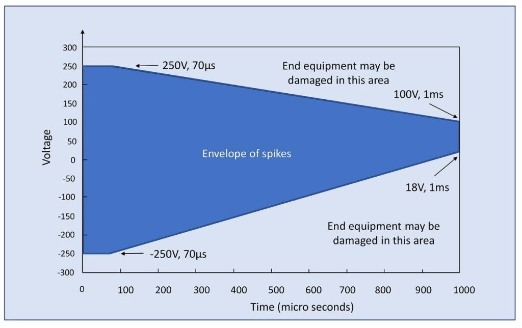
Considering MIL-STD 1275/F, immunity of equipment to short spikes is required with peak values up to +/-250V for 70s maximum, reducing linearly to values between +100V and +18V for 1ms. Maximum energy of any single spike is 200mJ (Figure 3).

Figure 3: Short spikes present on vehicle supply rails according to MIL-STD 1275/F
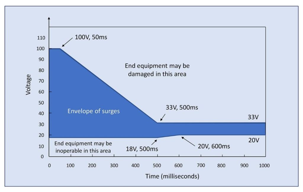
High energy surges can also be presentto +100V for 50ms, linearly reducing to >33V for 500ms while dips to 18V can last for 500ms reducing to <20V for 600ms (Figure 4).

According to the standard, ripple voltage can also be present at +/-4V peak-to-peak between 30Hz and 5kHz.
DEF-STAN 61-5 part 6 standard defines short repetitive transients of +100/-150V for 12V systems and +200/-200V for 24V systems. These last 100ns and repeat every 100µs in bursts of 10ms with gaps of 90ms. Exact waveshapes are described in the standard. Long transients according to the UK standard can be to +20V for 12V systems and to +40V for 24V systems, lasting 50ms.
A particularly onerous requirement is to withstand ‘load dumps’ – high energy surges produced when high current loads suddenly disconnect. In the UK standard, two situations are considered, a platform with no control of load dumps and one with a centralized load dump suppression system. At worst, connected equipment sees 202VDC in a 24V system (101VDC in 12V systems) for 400/350ms respectively from a low source impedance of 8/4 ohms respectively. The standard, however, does allow equipment to lose function as long as it is not damaged and can be restored after the event, by manual intervention if necessary.
Connected equipment must not be damaged by a reversed supply connection and not draw more current in reverse than the ‘normal’ value when connected with the correct polarity.
EMC requirements
For electromagnetic compatibility (EMC) in the US, MIL-STD 461 would apply, currently at revision G. In the standard, emissions and susceptibility limits are defined for different applications. For example, in the ‘ground, army’ category the following would be relevant:
CE 102: Conducted emissions – 10 kHz to 10 MHz
CS 101: Susceptibility – 30Hz to 150 kHz
CS 114: Susceptibility – 10kHz to 400 MHz
CS 115: Susceptibility – broadband impulses
CS 116: Susceptibility – damped sinusoidal transients
DEF-STAN 61-5 specifies that equipment shall meet DEF-STAN 59-411 Parts 1,3 and 4, service class A, unless agreed otherwise.
DC-DC converters connected to the vehicle supply cannot be expected to be immune to the spikes and surges specified, so will normally be preceded by a filter and ‘conditioner’ which could feed several downstream modules. An L-C EMC filter would enable compliance to high-frequency emissions and immunity standards and be transparent to the variation in nominals and surges while suppressing spikes to some extent. An example might be the Gaia FGDS-35A-50V part, rated at 35A DC in a board-mount package 41 x 27 x 16.7mm. A conditioner might then provide clamping of transients and surges to safe levels for the following converters or even switch off the supply rail for the duration of high-energy events that practically cannot be clamped. The conditioner will also typically include series low-loss switches to provide reverse polarity protection.
An example of a conditioner module suitable for the application is the Gaia LGDS-600P. Rated for 600W of output power, the board-mount module is just 40.7 x 48.5 x 12.7mm and clamps any of the specified spikes and surges to a maximum of 38V on its output, within the surge rating of following Gaia DC-DC converters. Voltages up to 202VDC are clamped while higher levels cause the conditioner to temporarily disconnect and automatically reconnect when the level has fallen. Small capacitors on the conditioner output provide ride-through energy for the duration. The module also includes additional functionality with the ability to synchronize downstream converters to a single clock, with two anti-phases available to minimize input ripple current and EMI signature. An undervoltage lock-out operates for low input voltages, with a warning signal available to switch the output to a back-up source if required.
An example DC-DC distribution system
Figure 5 shows an example system that meets MIL-STD 1275/F and MIL-STD 461. The MGDM-500 is a single-output device but could be replaced by multiple lower power modules from the same MGDM series to provide a range of mutually isolated DC levels of either polarity. The power limit is set by the 35A rating of the EMI filters and the 600W maximum rating of the bus conditioner.

Figure 5: A DC-DC converter system rated 500W compliant with MIL-STD 1275/F and MIL-STD 461 suitable for Vetronics applications
The Vetronics physical environment
Electronic equipment in military vehicles must operate in a difficult environment, with wide temperature swings, high shock and vibration, little or no airflow and subject to humidity and pollutants. DC-DC converters suitable for the application should therefore be robust and at the same time, have high MTBF and long service life. The MGDM-500 from Gaia referenced is a good example of a suitable part. In a half-brick format, it is encapsulated for physical protection and can be cold-wall mounted for heatsinking. The part meets MIL-STD 810G for shock, vibration, bump, altitude, humidity and salt atmosphere testing and MIL-STD-202G for temperature shock and cycling, and humidity resistance. MTBF is over 1.7 million hours at 40°C according to MIL-HDBK 217F. The MGDM-500 operates from -40°C to 105°C case temperature and is fully protected against overload, over-temperature and short circuits. Isolation is 1500VDC.
Conclusion
Effectiveness and survivability of military vehicles are attributes strongly reliant on the incorporated Vetronics. DC-DC converters generating associated vehicle power rails need to be efficient, flexible, scalable and reliable to match the increasing use of open design architectures and COTS products, while being compliant with military standards. Manufacturers such as Gaia Converter offer a complete solution with a wide range of compliant DC-DC modules, matching EMI filters and bus conditioners.
References
[1] https://www.alliedmarketresearch.com/vetronics-market
[2] https://www.gaia-converter.com


