Abstract
There are multiple approaches to adding more intelligence to industrial systems, including edge and cloud artificial intelligence (AI) matched to sensors with analog and digital components. With the diversity of AI approaches, the sensor designer needs to consider several competing requirements, including latency for decision-making, network usage, power consumption/battery life, and AI model fit for machines. The previous article focused on the overview and hardware design of Voyager4: a wireless, AI-based condition monitoring sensor. This article will focus on the software architecture and AI algorithm created for an intelligent edge sensor. A complete system-level approach for AI model development on the Voyager4 will be described.
Software Design of a Condition Monitoring Sensor
Voyager4 is a wireless condition monitoring platform developed by Analog Devices to enable developers to rapidly deploy and test a wireless solution to a machine or test setup. Motor health monitoring solutions such as Voyager4 are used across the industry in fields such as robotics and rotating machines such as turbines, fans, pumps, and motors.
Developing the software for such a wireless edge device can be difficult. From early in the sensor’s design, the developer must consider the overall system architecture, accounting for how individual parts of the system will operate, how the different components will be integrated to work together, and how useful algorithms and analysis tools such as neural networks can be applied and deployed to add intelligence to the edge.
The goal for any such project is to create software for the edge device and the connected host, which is easy to understand, modifiable, and upgradable. Within Voyager4, there are two microcontrollers and many peripheral devices including sensors, power management boards, flash memory, and communication interfaces. Developing the code required to control and combine each of these pieces is a daunting task.
The hope for this article is that by showcasing the design process that was used during Voyager4’s development, highlighting the steps taken and giving some specific imple- mentation examples, the reader can form a better understanding of how to develop their own edge sensor.
This is Part 2 of a 3-part article series documenting the development of the Voyager4 condition monitoring platform.
- Part 1 of this article series introduces the Voyager4 wireless condition moni- toring sensor, including key elements of sensor architecture, hardware design, power profiling, and mechanical integration.
- Part 2 of this article series will focus on the software architecture and AI algorithm. A complete system-level approach for AI model development and deployment on the Voyager4 will be described.
- Part 3 of this article series will look at the practical implementation of the AI algorithm and the different faults Voyager4 can detect such as imbalance, misalignment, and bearing defects.
Overview
While a brief recap of the Voyager’s operation is given here, refer to Part 1 of the article series for more information on condition monitoring sensors and greater detail on the unique hardware, power, and security features of the Voyager4 project.
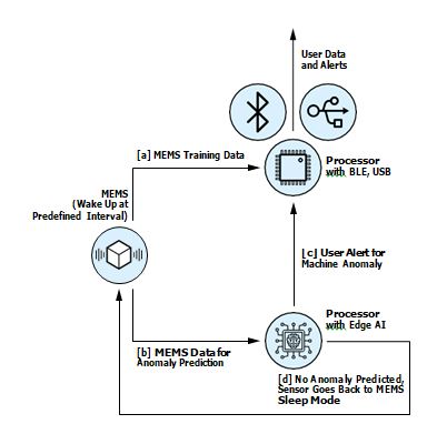
The sensor operating principle for Voyager4 is presented in Figure 1. The ADXL382 triaxial 8 kHz digital micro electromechanical system (MEMS) accelerometer is used to gather vibration data. Based on the mode of operation, the data gathered may follow several different paths.
Path A is the path initially taken with raw vibration data being sent directly to the MAX32666 Bluetooth® low energy (BLE) processor. From here, the data can be sent to the user over BLE radio, or via USB. Path B is an alternative mode of operation that can be used once raw data has been gathered using the Voyager and a model is trained using the MAX78000 external tools. Data is not sent to the user but is instead passed to an edge AI algorithm to predict faulty machine data. Paths C and D cover the use cases in which a motor fault is detected or not detected, respectively. If a fault is detected, a flag or user alert may be sent via the BLE processor to the host. If a fault is not detected, the sensor instead goes back into Sleep Mode until the next detection event.
This architecture is the focus for the software and AI algorithm development for Voyager4. For a complete system-level understanding of this architecture, this article will discuss:
- BLE terminology
- Implementation of BLE peripheral
- Implementation of BLE central
- Training and deployment of the AI algorithm
BLE Background
When designing an industrial edge sensor, connectivity is one of the key design factors. This affects everything from range and reliability to the overall life- time and size of the device, based on the power available/required. As shown in Table 1, BLE has some unique advantages when compared to other connectivity standards. Range, power, and reliability of BLE were particularly important to our use case of industrial monitoring. To understand the design and development of a BLE edge device, you must first understand some of the basic terminology used by any BLE project.
Table 1. Comparison of Wireless Connectivity Standards
A thorough explanation of all that BLE has to offer would fill a book, so instead this article focuses on some of the key concepts that anyone implementing a BLE device needs to consider, namely:
- Software stack
- Peripheral/central model
- Protocols and profiles
BLE Software Stack
The BLE software stack is a collection of standard protocols that must be imple- mented by a device for it to be considered BLE compatible. The name is more easily understood in Figure 2, by illustrating how different protocols within the stack are layered. High level functionalities like user communication and device connection are supported by lower level protocols responsible for fundamental tasks such as data encapsulation and parsing.
Fortunately, a basic understanding of the components of the stack is often enough for developers, who can choose from a range of hardware devices that have implemented their own versions of this. This requires the user to simply develop part of the application that will control the device itself while making use of a prebuilt BLE stack.
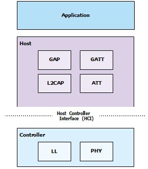
The BLE stack is often represented as three distinct parts: application, host, and controller. The application defines the interface to the user and the specific application code (vibration monitoring) that the user is implementing. The host refers to the upper layers of the BLE software stack, which controls the high level functionality such as profiles and protocols. The controller refers to the lower layers of the BLE stack, which deals with the link layer and the physical layer like the 2.4 GHz radio itself. For this project, the MAX32666 BLE microcontroller was chosen. This is a low power Arm® Cortex®-M4 microcontroller with a Bluetooth 5 LE radio with support for long range (4×) and high data throughput (2 Mbps).
Peripheral/Central Model
A BLE device may be defined as either a peripheral or a central depending on its role. As data can flow in both directions, one of the biggest differentiators between the two is in how they connect. Before connection, peripherals advertise their availability to connect. Central devices scan for available peripherals to connect to and initiate the connection. Data may flow in both directions between peripheral and central, but the central is regarded as the host. Older BLE references also refer to peripherals and centrals as servers and clients, respectively.
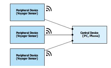
In our system, the Voyager platform is defined as our peripheral, which gathers and sends data to a central. For this project, to simplify development and for ease of understanding, initially the focus is on the simplest case of a single central interacting with a single peripheral as shown in Figure 3.
Protocols and Profiles
Protocols and profiles are an easily confused portion of Bluetooth’s naming termi- nology. Simply stated, protocols are basic functional building blocks that define device operation: data encapsulation, format, routing, etc. Profiles are bundles of functionality that combine to enable basic modes of operation. It is essentially a combination of protocols to achieve a certain overall function, for example, a battery service profile, which can be used to interrogate the remaining battery of a device. The all-important Generic Access Profile (GAP) and Generic ATTribute Profile (GATT) must be implemented by all BLE devices to allow them to connect to other BLE devices. GAP covers the low level functionality—advertising, device discovery, and managing connections. GATT manages the high level data orga- nization and transfer between devices, allowing them to read and write over an established connection.
Other profiles are optional add-ons for additional functionality to a device like a Proximity Profile. This includes predefined profiles created by the Bluetooth Special Interest Group (SIG). Using a predefined set of profiles may be useful when developing a typical device such as a smart watch or smart meter but can be restrictive for devices that implement a lot of custom functionality.
Custom profiles not defined by the Bluetooth SIG are also permitted, giving greater design flexibility at the cost of portability. Each profile organizes its data into services, which consists of several characteristics as shown in Figure 4.
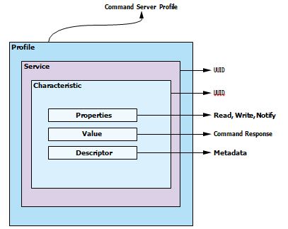
When a connection is formed between central and peripheral, the central device can request the profiles and services associated with that peripheral. Figure 5 shows the structure of the GAP, GATT, and custom profiles (and their services) of Voyager when requested by central.

For Voyager, we define the basic GAP and GATT profiles in addition to a single custom profile that is used as a command server, where commands from the central are processed and data is returned or the configuration of the peripheral itself is updated.
Firmware Implementation
The BLE microcontroller is the heart of the system, ensuring that data from all the peripheral sensors and devices is available for retrieval or modification by the connected BLE central.
Device Configuration
With the BLE stack prebuilt on the MAX32666, we build our peripherals’ appear- ance by filling out the relevant configuration functions. For example, in Figure 6, we provide a data length, advertising type, and a list of characters to our scan data discovery array, which is called in our peripheral setup function every time the Voyager is powered up.
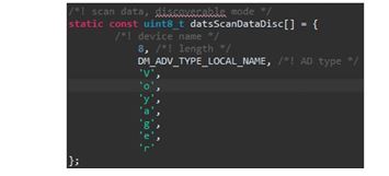
A BLE device such as this will have a huge number of settings to configure, includ- ing transmission power from the radio and return data types. It is advisable to start with any prebuilt examples available with the hardware you are using and to make custom modifications from there. The MAX32666 offers an example code for a BLE data server (peripheral) called BLE DATS that was used as the basis for the Voyager project. After configuration, when the central scans for available devices, the peripheral’s name appears as Voyager. This can also be used to filter the search list so that the central displays only devices of the expected name. As seen in Figure 7, the device name is displayed alongside the device MAC address and the received signal strength indicator (RSSI).

Other configuration settings within the stack control the expected names and behaviors for other modes of the device such as manufacturer ID, responses to read/write commands, etc.
The Command Server
As the central and peripheral sides of the Voyager4 application were designed in tandem, the peripheral interface can be simplified by making use of a cus- tom profile with a single BLE service. This profile will be responsible for receiving commands from the central device and returning responses in the form of accel- erometer data, temperature data, and other device information.
This single custom service is unorthodox for BLE communication in a device as complex as Voyager but has several benefits. It enables backward compatibility between Voyager versions and improves command flexibility, as using strings as the command input to the Voyager peripheral allows for a variety of command types and values based on how the data is parsed.
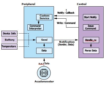
Once a connection is formed between peripheral and central, to establish bidi- rectional communication the central will issue a notify command to the custom characteristic as seen in Figure 11. This establishes a notification system on the peripheral side and assigns a corresponding callback function on the central side. This means that any time there is updated data assigned to that custom charac- teristic, the central device is notified, the new data is transferred, and the central device’s callback function is triggered.
Firmware Architecture
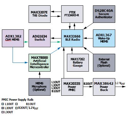
The hardware diagram in Figure 8 shows the array of content, included in the Voyager, and the relative data paths and power supplies. Most of the software development took place on the BLE microcontroller, as this operates as the command center, coordinating both the BLE interface to the device and the internal pipeline of sensor and microcontroller data. To interact with the different sensors and micros in our system, we must develop device drivers to be used by the BLE microcontroller, and the AI microcontroller as discussed in the AI section. In practice, the development and integration of these drivers is a large portion of the coding work required for a connected edge sensor.
Writing Portable Code
While developing our firmware we divided the code into several layers of abstraction, separating the specific details for one specific microcontroller from the application and driver code. This is a well understood problem and is often tack- led by separating code responsibility into three distinct layers in addition to the application layer. These are the hardware abstraction layer (HAL), board support package (BSP), and the driver layer. This architecture is shown in Figure 9.
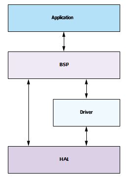
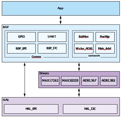
The HAL provides a uniform way for programs to interact with different hard- ware without needing to know the details of each device. The BSP defines the hardware-dependent software, and the driver layer defines the finer details of individual devices such as register mapping. For example, within Voyager we have two microcontrollers, the MAX32666 for BLE connectivity, and the MAX78000 with an on-board convolutional neural network (CNN) accelerator. As shown in Figure 10, the HAL in Voyager defines the most basic communication commands that will be used by either of the microcontrollers, SPI and I2C. As an example, any SPI call issued by any of the device drivers will initially defer responsibility to the SPI functions in the HAL, which then looks up the specific information for the BSP to use the correct SPI command for that microcontroller.
The HAL remains the same for every board in the system, but the BSP is updated for each microcontroller. The BSP is also responsible for defining the generic building blocks of the system, which decouple application calls from the specific device used. In Figure 10, the MAIN_ADXL block in the BSP is an abstraction from the underlying accelerometer used. Common commands for any accelerometer such as Initialize and Read are defined within the BSP layer, while low level functions such as get_raw_xyz_data are defined at the driver level in the ADXL382 block. When porting the driver code from the MAX32666 to the MAX78000 micro- controller, the accelerometer code remains unchanged as it relates only to the accelerometer itself. The only files updated to allow communication with the new microcontroller are within the BSP layer.
This also has clear benefits in terms of replacing or upgrading parts in the system. One real example of this within Voyager was the decision to upgrade the main accelerometer used. In this case, only the code within the driver layer was updated, simplifying maintenance, modification, and testing.
Data Pipeline and BLE Central
While temperature and battery information are made available to the BLE central application on request, Voyager’s primary role is as a condition monitor and vibra- tion sensor. Our requirements in terms of data throughput and how often data must be sent will be focused on the vibration sensor and a typical condition moni- toring setup, for instance, one short measurement once a day. BLE does not allow a high data throughput. The ADXL382 is a high bandwidth, 3-axis accelerometer gathering 16,000 samples per axis every second in high performance mode. There are a few available options for sending data based on the components included in the system.
Sending Live Data
Without any form of buffering, send data as soon as it is available while it is being requested by the central. While this is useful as a demo mode, showcas- ing the high performance accelerometer data in real time, the battery is quickly consumed, and data packets are dropped or corrupted as the amount of data generated exceeds the rate at which it can be sent.
Sending Data from Memory
Another option is to save the data to flash memory. In this way, we can safely record the accelerometer data without fear of overwriting previous values. The saved data is then sent directly to the central or reported out upon receiving a command from the central. As this system is no longer real time (data could be minutes or even days old), we can also make use of the BLE acknowledgment system for packets, ensuring that data arrives fully intact at the central, and resending any lost data.
This solution is much more practical for a typical industrial condition monitoring setting, but the device’s battery life is mostly wasted sending vibration informa- tion that does not change much day to day.
Performing Analysis at the Edge
To save on battery life, it is better to perform some analysis at the edge to ensure that only relevant data is communicated over the radio link. Of course, this is only possible if the power required to create meaningful insights at the edge is significantly less than that required to send the data over BLE (see Part 1 of this article series for further information on this). In Figure 8, you can see that the accelerometer has a direct data path to both microcontrollers. In the use case where we will perform some analysis at the edge, the AI microcontroller can directly read vibration data from the accelerometer and perform an analysis with an onboard AI model.
Designing the Central User Interface
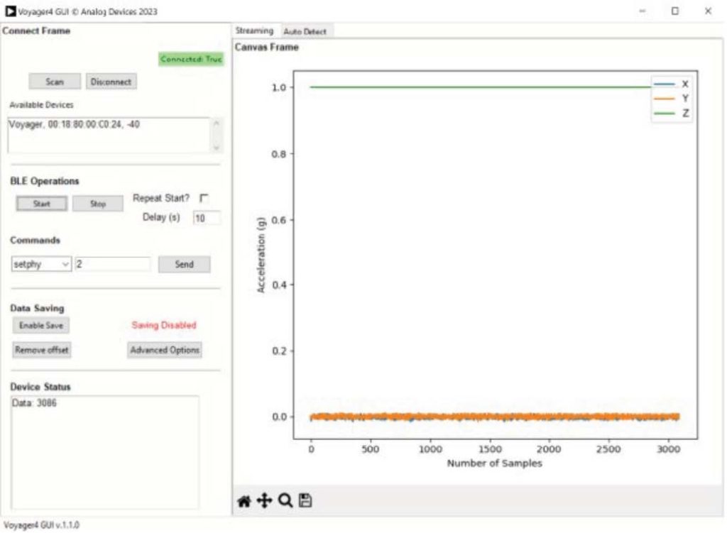
As the BLE peripheral was designed in tandem with the Voyager peripheral, there was a lot of flexibility in how the two interacted. In general, the central device needed to scan for and connect to a Voyager peripheral, and then send string commands and process their return values. After the initial connection, all BLE commands are sent directly to the peripheral’s custom service for parsing. The central in this case is a graphical user interface (GUI) on a Windows PC, written in Python, and making use of a BLE peripheral library (BLEak) to issue standard BLE commands. BLEak was built on top of the standard asyncio library for Python, allowing BLE commands to run asynchronously, ensuring the user interface remains interactable and does not freeze.
When the GUI successfully connects to a peripheral, a notify command is issued automatically to the single custom characteristic of the Voyager as displayed in Figure 11. This ensures that any updates to this characteristic are reported to central. This is important, as further commands receive an acknowledgment or response from the Voyager that indicates if they were successfully carried out.
How Is Data Requested?
Data is always requested using simple string commands. For example, central may issue a setphy 2 command to instruct the Voyager to use its 2M radio, which enables faster data communication at the cost of some range and reliability. The peripheral device parses this command to ensure it is valid, before calling its own internal setphy function with an input value of 2 to switch the radio used. If this function is carried out successfully by Voyager, a Return: OK command is issued back to the central device and displayed to the user.
Interpreting Accelerometer Data
Before receiving data, the user of the GUI may optionally configure the accelerom- eter of the connected Voyager using the setadxlcfg command. Once the peripheral issues a start command, the flow of accelerometer data from peripheral to central begins. By default, central and peripheral devices operate in live data mode as this is useful for demo purposes.
On the peripheral side, the internal first-in-first-out (FIFO) buffer is filled with the latest data at the user specified sampling rate. Once the FIFO is filled, a flag is placed on the Voyager custom service, notifying the peripheral that new data is available. Data is then sent to and parsed by the peripheral, into formatted arrays of acceleration data in three axes: x, y, and z. Data is always plotted, and the user may optionally select a Save data option that also saves the same data to a csv file for later analysis.
AI Algorithm Design
The goal of this project is to detect when a motor’s health begins to degrade. AI analysis at the edge seeks to replace or supplement human analysis of the data, by creating metrics or characterizations of motor health, based on one or more inputs including audio, temperature, and vibration. Vibration is by far the most utilized in condition monitoring applications today.
Inputs
Many edge AI processors tend to be quite power hungry, which runs counter to one of the goals of any wireless condition monitoring solution: long device lifetime. The MAX78000 (as stated earlier) can make fast, low power AI inferences that use less power overall than making use of the BLE radio. However, in using a low power edge AI processor, keep in mind that the size of our neural network cannot exceed the specifications of the board. The board features a CNN accelerator with 512 kB of data memory. It is primarily intended for object detection, audio processing, and time series data processing.
The available data for our solution is acceleration over time. To maximize the performance of the trained algorithm, several preprocessing approaches were trialled to determine which had the greatest effect on accuracy. This is discussed in greater detail in Part 3 of this article series.
Training
The process for training and deploying a neural network to the MAX78000 is well described online through the “Analog Devices AI” GitHub. In general, a model is first created on a host PC using conventional toolsets like PyTorch® and TensorFlow®. This model requires training data that must be saved by the targeted device and transferred to the PC. One subsection of the input becomes the training set and is specifically used for training the model. A further subsection becomes a validation set, which is used to observe how the loss function (a measure of the performance of the network) changes during training.
Depending on the type of model used, different types and amounts of data may be required. If you are looking to characterize specific motor faults, the model you are training will require labeled data outlining the vibrations present when the different faults are present in addition to healthy vibration data where no fault is present.

Voyager was initially developed with an autoencoder type neural network. Autoencoders do not need the data to have any labels to learn how to classify it. While this type of model is not suited to complex fault classification, it can be quickly trained and uses only data that the customer already has on hand like healthy motor data.
Finding the ideal amount of data to train on is unique to every case, with sufficient data required to learn the general trends of healthy motor data without overfitting the data to the training input. The default example deployed with Voyager was trained with just 30 seconds of healthy accelerometer data. The same amount of data with an imbalance fault present was saved for verification. Both datasets were saved directly to the training PC using the Python GUI.
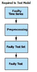
Before being used to train the model, the input data was pre-processed. The train- ing script then runs through several iterations of the training sequentially and chooses the best performing model. Some faulty input data is required for testing purposes. You cannot train a model on healthy data and express confidence in your results without first testing on example faulty data.
How Is the Algorithm Deployed?
Once the model is trained, it must be quantized and synthesized using ADI’s online toolset. Quantization adjusts the weights of the generated model to a smaller set of bins by rounding or truncation, allowing for a reduction in the memory required to store the model. This is a standard procedure when deploying neural networks to smaller edge devices. Synthesis converts the quantized model into c files that can be understood by the microcontroller.
Three files are generated, which must then be copied into the active project for the microcontroller and loaded with the next firmware update. Two of the files (cnn.h and cnn.c) contain register writes for CNN configuration and other use- ful functions for the model that is loaded. The third file (weights.h) contains the trained (and quantized) model weights.
Once the new firmware is loaded, either via a wired update over the debug port, or wirelessly with an over-the-air (OTA) update, the model has been deployed and can be queried by the BLE microcontroller to make AI inferences on demand.
How Is It Used Once It Is Deployed?
Once the new firmware is deployed, the AI microcontroller operates as a finite state machine, accepting and reacting to commands from the BLE controller over SPI.
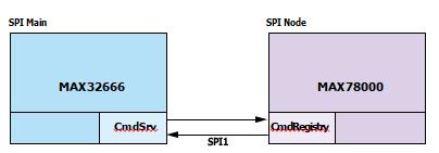
When an inference is requested, the AI microcontroller wakes and requests data from the accelerometer. Importantly, it then performs the same preprocessing steps to the time series data as used in the training. Finally, the output of this preprocessing is fed to the deployed neural network, which can report a classification.

As a battery saving measure, the AI microcontroller is designed to automatically issue an inference upon wakeup, which allows the BLE microcontroller to power it up only when an analysis is required.
In a typical setup, the BLE microcontroller can wake from a low power sleep mode for a short period every day, request an AI inference of the accelerometer data present, and return to its sleep mode if the data does not pass a user-set criteria such as the model states that the data looks healthy with 99% certainty. In the opposite case, where data looks anomalous or cannot be confidently identified as healthy, the BLE microcontroller can connect to a nearby BLE host and share the data. In this way, the analysis at the edge removes the burden of understanding the data from the host system and saves battery life as a result.
Conclusion
In this article, we introduced Voyager4, a wireless vibration monitoring system that employs edge AI analysis to improve its intelligence and lifetime as a condition monitoring tool. Designing an effective condition monitoring sensor requires several considerations. We discussed the hardware signal chain for Voyager4, and the firmware that was used to integrate different system elements together in addition to the external appearance of the device as a BLE peripheral. We also explored the use of AI in Voyager, giving some insights into how to consider developing and deploying your edge AI models.
Read on to Part 3 of this series to learn more about the specific implementation of the AI algorithm on board Voyager including the classification of several com- mon motor faults.
About the Author
Tom Sharkey is a systems applications engineer working in the Industrial Edge, Motion, and Robotics Unit at Analog Devices. Tom received a bachelor’s degree in electronic and computer engineering from the University of Limerick in 2020. He has experience in condition monitoring sensors, firmware/software design, and motor control.


