Abstract
In many applications, it is crucial to safeguard against overvoltages. This article explains how overvoltages can be neutralized with a protective circuit.
Introduction
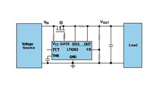
Overvoltages can be caused, for example, by the rapid switching off of a high load in a power distribution system. Surge protection is recommended to protect other loads that are connected to the same power supply. Figure 1 shows the arrange- ment of a protection circuit, using the LT4363 in front of the electronic circuit to be protected. The example is from an industrial application where the nominal supply voltage is 24 V.

Normally, the electronics to be protected should continue to operate without inter- ruption during an overvoltage. This requires the protective circuit to operate the circuit breaker (Q1 in Figure 1) in the linear range. The MOSFET is neither switched off nor switched on during the occurring overvoltage. It is partially switched on. In this operating state, it behaves like a resistor across which the overvoltage drops. The energy of the increased voltage is thus converted into heat in MOSFET Q1. Depending on the selection of the MOSFET, it can only withstand this heat for a certain time before it is destroyed by excessive heat.

Figure 2 shows a typical safe operating area (SOA) curve of a MOSFET. This curve defines how long the device can carry which current at which voltage drop. If you want a higher current to flow through the MOSFET for a longer period, a larger MOSFET with a larger SOA range must be selected. The larger the SOA range, the larger the MOSFET. This also increases the cost of the component.
To size the component optimally, an attempt is made to operate the smallest possible MOSFET safely. This means that it is not oversized and yet a large part of its SOA can be used in the application. This requires the controller IC to precisely recognize the operating state to determine whether the operation is taking place in the safe range of the SOA. However, many controller ICs only measure the cur- rent flowing through the MOSFET. It is better to also know the voltage drop across the MOSFET.

An LT4363 surge protector component not only considers the level of the current through the MOSFET, but also the voltage applied between the source and drain. This means that the MOSFET can be operated more safely in linear mode. This can lead to the selection of a smaller MOSFET and lower system costs.
The protection mechanism works by charging the timer capacitor at the TMR pin in Figure 1, depending on the measured current and the measured drop-out volt- age. If the voltage at the capacitor rises above 1.275 V, a warning is generated. Above 1.375 V, the MOSFET is switched off completely to protect it.
Figure 3 shows how the voltage on the timer capacitor of the LT4363 in Figure 1 rises due to the VDS voltage on the MOSFET Q1 in Figure 1. There is a similar charging diagram for the current flowing through the MOSFET Q1. These parameters ensure that the SOA curve of a MOSFET is not exceeded. Safe opera- tion and simultaneous overvoltage protection are thus achieved.
Conclusion
Overvoltage protection modules appear quite simple and unspectacular. However, small features can make a big difference in the behavior of the overvoltage pro- tection and in the selection of a suitable MOSFET.
About the Author
Frederik Dostal is a power management expert with more than 20 years of experience in this industry. After his studies of microelectronics at the University of Erlangen, Germany, he joined National Semiconductor in 2001, where he worked as a field applications engineer, gaining experience in implementing power management solutions in customer projects. During his time at National, he also spent four years in Phoenix, Arizona (U.S.A.), working on switch-mode power supplies as an applications engineer. In 2009, he joined Analog Devices, where he has since held a variety of posi- tions working for the product line and European technical support, and currently brings his broad design and application knowledge as a power management expert. Frederik works in the ADI office in Munich, Germany.


