Abstract
Advancing technology comes with lowering the core voltages of digital computing devices like FPGAs, processors, DSPs, and ASICs to address the power consumption and thermal challenges that affect its performance. This also leads to tighter core supply tolerances, which narrows down the operating voltage range. While most of the switching regulators are not perfect, this trend of core voltages calls for a very accurate power supply for proper operation.1 Window voltage supervisors help ensure that devices operate in proper core voltage levels, however threshold accuracy is a great factor in maximizing the usable power supply window.2
This article discusses how using a high-accuracy window voltage supervisor maximizes power supply out- put. By improving the window of usable power supply for core voltages o1f devices, it ensures operation within the valid operating power supply range.
Introduction
Energy consumption of digital circuits is one of the major con- cerns as the demand for portable and battery-operated gadgets and devices is vastly increasing. Computing and processing are getting more complex, which requires faster devices such as field programmable gate arrays (FPGAs) and other processing chips. Complicated processes demand higher power, which in turn causes fast chips to heat. Figure 1 shows that the process technology trend in device dimensions is scaling down to the nanometer range, which necessitates a corresponding reduc- tion in operating voltages, optimizing processing speed and expanding the operational lifespan of devices.3
With this trend of technology process optimization, highly accurate power supplies are then required. If the actual performance of the power supplies is not considered, then it can lead to system performance risks. Since most regulators are not accurate enough, if the core voltage falls below the operating requirement, processing devices (FPGAs for instance) risk failure due to errors. And with continuous operation, if the core voltage drifts above the maximum operating requirement, this can damage the FPGA and create hold-time failures in the logic. All these risks can come with load condition, operating temperature, and aging.1 While FPGAs are mentioned for most of the examples in this article, the same principle applies for other computing and processing devices.

Dealing with Tolerances
Tolerance needs careful attention when designing and monitor- ing power supplies for computing and processing chips as it can be treated differently from each perspective. In this article’s dis- cussion, we define each tolerance in the following sections.
Core Voltage Tolerance
The core voltage tolerance is the computing device core supply specifications. Table 1 shows the Altera Arria 10 FPGA core volt- age specifications as an example. The minimum and maximum values range amounts to ±3.3% tolerance with respect to the nominal value. Operating this device below the standard mini- mum or above the maximum will lead to performance issues. For optimum performance and low power operation, a tighter toler- ance is required.
Table 1. Altera Arria 10 Core Voltage Specification
| Symbol | Description | Condition | Min | Typical | Max | Unit |
| VCC | Core Voltage Power Supply | Standard Power | 0.87 | 0.9 | 0.93 | V |
| Low Power | 0.92 | 0.95 | 0.98 | V |
Power Supply Tolerance The power supply tolerance is the output deviation or output regulation performance of the power supply. To obtain a tight power supply tolerance requires expert design. However, it can change over time due to several external factors such as deterio- ration of components. In application, this power supply tolerance should be within the core voltage tolerance. Any operation of the power supply output can cause problems to the processing and computing device, such as in FPGAs. A regulator with a declared tolerance may not operate exactly at the middle of the output voltage regulation specification, but just within the regulation range. This can be due to the DC error brought by the standard value of resistors used in the feedback loop, which has inherent tolerance, robustness of reference voltage, and optimization of the feedback loop compensation. Consider an FPGA whose core voltage is supplied by a switching regulator as an example. This switching converter with a declared tolerance of ±2% may oper- ate anywhere within the 4% window. It can be below the nominal value but still within the -2%, therefore putting an FPGA at risk of timing problems. Or it can be near the +2% ceiling, which can still meet the FPGA requirement but is not optimum and wastes a lot of power.1 Leaving this unmonitored, the device may eventually operate outside of the recommended voltage levels, which can lead to more serious problems and must be avoided.
Window Supervisor Tolerance
The window supervisor tolerance, or tolerance window, sets the undervoltage (UV) and overvoltage (OV) threshold in terms of percentage with respect to nominal value. For a window voltage supervisor with a nominal voltage value of 1 V and a tolerance window of ±3%, the UV threshold is set at 1 V × 0.97 and the OV threshold is set at 1 V × 1.03. These thresholds, the UV and OV, however, have their own tolerances known as threshold accuracy.
Using Window Voltage Supervisors
A window voltage supervisor ensures that devices operate within their specified voltage range by setting UV and OV thresholds. It issues a reset output signal if the supply voltage falls outside these set limits, helping to prevent system errors and protect electronic devices from damage. A timing diagram in Figure 2 shows how a reset output is provided when a monitored voltage falls below the UV threshold or exceeds the OV threshold. There are several architecture options of window voltage supervisors for setting the UV and OV threshold and choosing the operating tolerance that can be selected for optimum operation.2

needs to be carefully selected from a range of available variants. Additionally, reset thresholds for UV and OV come with their own accuracy specifications. Threshold accuracy, typically expressed in percentage, is the degree of the conformance of the actual to the computed or target reset threshold, which is determined by a resistor divider and bandgap circuit in the integrated circuit (IC) design.4 The more robust the reference voltage and the resistors become, the higher the accuracy that can be achieved. Figure 3 shows an illustration of the tolerance window and threshold accuracy in a window voltage supervisor. The actual thresholds of UV and OV, which are the UV_TH and OV_TH, respectively, can vary within the accuracy specification of the minimum and maximum value.

accuracy specification.
Power supply performance budgeting is often done during sys- tem design. For an FPGA core voltage with ±3% tolerance or operating specification, ±1% can be allotted to power supply DC regulation error, ±1% to the output ripple voltage, and another ±1% allowance for transient response. Using a less accurate power supply with ±2% regulation error will leave less allow- ance for transients. This increases the risk of malfunctions to the device when directly supplied, as transients can go outside the core voltage specification window. Errors can be avoided by using window voltage supervisors to safely put the FPGA in reset mode when this happens.
Choosing the Right Tolerance Window
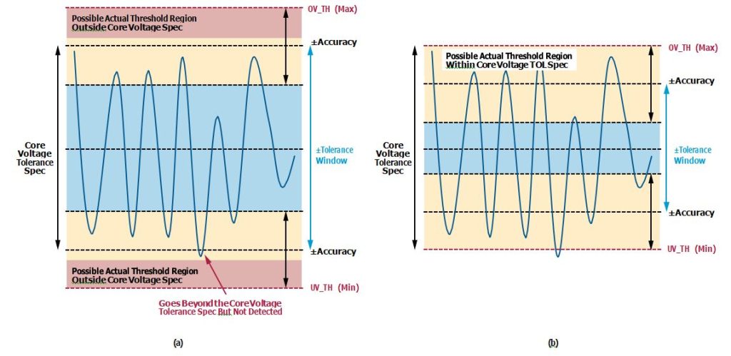
One of the common difficulties in using a window voltage super- visor is setting and selecting the appropriate tolerance window. Users tend to choose a window voltage supervisor with the same tolerance as the core voltage requirement. For example, a window voltage supervisor with a tolerance window of ±3% is used for a core voltage requirement that has a ±3% tolerance. Due to threshold accuracy, choosing the same tolerance with the operating requirement of the FPGA core voltage can trigger a reset output anywhere near the maximum overvoltage thresh- old OV_TH (max) and minimum undervoltage threshold UV_TH (min), leading to a potential malfunction. In Figure 4a, the moni- tored power supply could go beyond the core voltage tolerance and may not be detected by the supervisor on its possible actual operating threshold if threshold accuracy is not considered. This power supply going beyond the ±3% will be supplied to the core of a microprocessor, thus, a more appropriate choice of toler- ance window needs to be chosen. To avoid the risks of such a condition, the OV_TH (max) and the UV_TH (min) should be set within the ±3% tolerance requirement of the core voltage. Yet, a portion of usable power supply window will be eaten by accu- racy, which will give a reduced power supply operating window, as shown in Figure 4b.


The Impact of the Threshold Accuracy
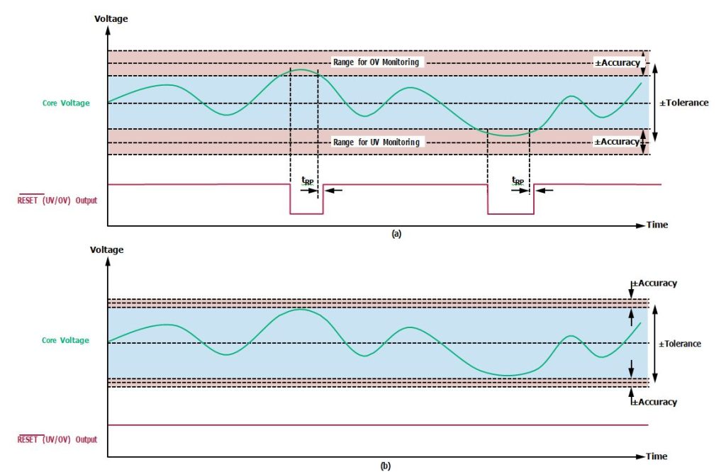
Consider two window voltage supervisors with different thresh- old accuracies to monitor the same core voltage supply. The actual UV and OV thresholds of the one with higher accuracy deviate less than the one with lower accuracy with respect to the expected UV and OV threshold values. From Figure 5a, note that a lower threshold accuracy will give a narrower power sup- ply window since the reset output signal will assert when the core supply voltage is anywhere within the UV and OV monitor- ing range. In applications with low accuracy power supply and poor regulation, this could lead to a more sensitive system that is prone to oscillation. Meanwhile, high threshold accuracy gives an expanded and wider usable power supply window, which improves system performance by operating stably, such as in Figure 5b.

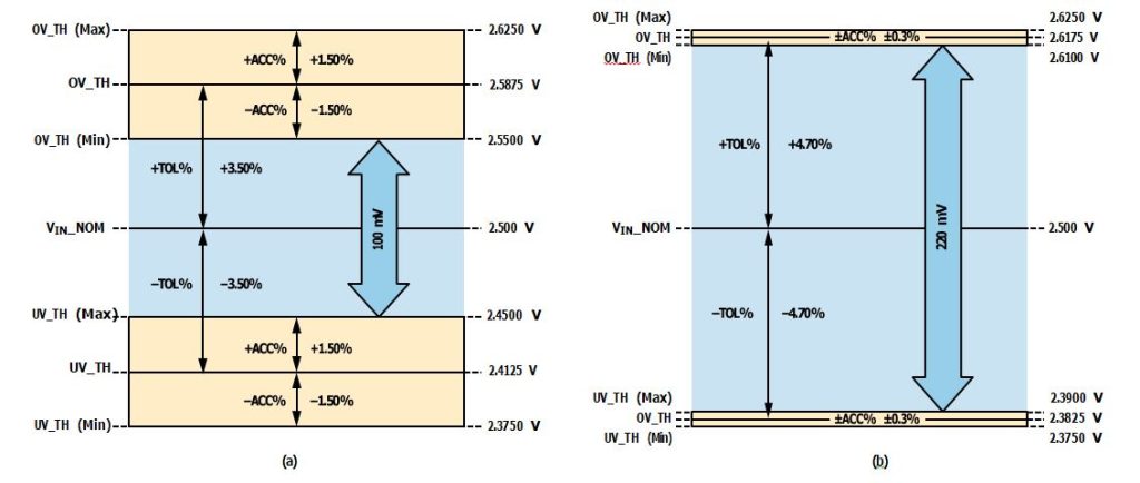
Figure 6 illustrates an example of monitoring a 2.5 V core volt- age with ±5% tolerance specification using two window voltage supervisors with different threshold accuracies. The tolerance window used in this example may not be the actual available options but were chosen to account for the threshold accuracy. The window voltage supervisor used has a threshold accuracy of ±1.5% and ±0.3% for figures 6a and 6b, respectively. When using a ±1.5% threshold accuracy, the optimum tolerance window to avoid operating in a malfunction region shown in Figure 6a is ±3.5%. This results in a power supply operating window of 100 mV. While with a ±0.3% threshold accuracy, the optimum tolerance window that maximizes the power supply is ±4.7% without any malfunc- tion risks. These values set will give a power supply operating window of 220 mV. This difference in the accuracy improves the operating power supply window by more than double, maximiz- ing the power supply performance.
The above calculations were obtained using the Window Voltage Monitor Calculator, a tool that aids to easily understand and visualize the different parameters in a window voltage supervisor. This also allows users to check whether the device specifications fit the design requirements such as the power supply operating window. This tool is available for download from the following product pages: MAX16138, MAX16191, MAX16193, MAX16132/MAX16133/MAX16134/MAX16135, MAX16137.
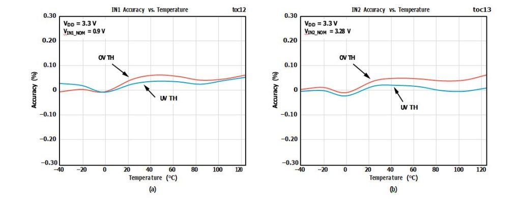
With continuous improvement in the architecture and performance of window voltage supervisors to address the demand of core voltages getting lower, threshold accuracies can now range from as high as ±1.5% to ±0.3%. And to enhance precision, window voltage supervisors with a factory-trimmed nominal monitored voltage and tolerance window are available.2,5 The MAX16193, a ±0.3% accuracy dual-channel supervisory circuit, is the industry’s window voltage supervisor with the highest threshold accuracy across different temperatures as of year 2024. A variety of factory-trimmed tolerance windows from ±2% to ±5% are available to accommodate different supply voltages and tolerances for industrial and automotive applications. In the typical application circuit in Figure 7, input channel 1 (IN1) monitors low core voltage rails from a 0.6 V to 0.9 V threshold range with ±0.3% accuracy, while input channel 2 (IN2) monitors higher system rails from a 0.9 V to 3.3 V threshold range with ±0.3% accuracy. The MAX16193’s threshold accuracy specification is true for all tem- peratures within the operating range of -40°C to +125°C. Figures 8a and 8b show that the high threshold accuracy of the device for the two inputs IN1 and IN2 is true at different temperatures. While other voltage supervisors have the optimum performance only on certain range, this device guarantees high accuracy from the minimum up to the maximum operating temperature.

Conclusion
To keep up with the demand in speed, power optimization, and along with advancing process technology, core voltages of devices are getting lower, and the tolerance is getting tighter. Window voltage supervisors help prevent serious problems in these devices. However, threshold accuracy plays a great part in operating within the device specification window. High thresh- old accuracy of window voltage supervisors helps maximize the power supply performance by improving the operating power supply window, thus preventing unwanted frequent resets and system oscillation.
References
1Nathan Enger. “Care and Feeding of FPGA Power Supplies: A How and Why Guide to Success.” Analog Dialogue, Vol. 52, No. 11, November 2018.
2Camille Bianca Gomez and Noel Tenorio. “Optimize Your System Design with the Right Window Voltage Supervisor.” Analog Dialogue, Vol. 58, No. 3, September 2024.
3Mohammed Mahaboob Basha, Kota Venkata Ramanaiah, and Palakolanu Ramana Reddy. “Design of Near Threshold 10T- Full Subtractor Circuit for Energy Efficient Signal Processing Applications.” International Journal of Image, Graphics and Signal Processing, December 2017
4Noel Tenorio. “How Voltage Supervisors Address Power Supply Noise and Glitches.” Analog Dialogue, Vol. 57, No. 4, November 2023.
5“Voltage Monitors and Supervisors Product Highlights.” Analog Devices, Inc.
6“Keep the Product Working-Microprocessor Supervisors Offer Big Insurance in Small Packages.” Analog Devices, Inc., November 2001.
7Pinkesh Sachdev. “Design Note FPGA Power System Management.” Analog Devices, Inc., March 2020.
8Caroline Hayes. “Designing Supply Voltage Supervision for Multirail Boards.” Electronic Specifier, October 2015.


