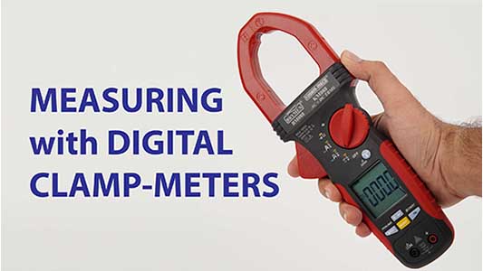
Current measurements have been simplified by the introduction of the clamp-on ammeter, which allows readings to be taken without breaking the circuit. This article outlines how such instruments work and how to get the best out of them.
Until recently the measurement of current was not as straightforward as that of voltage. Measurements were made by breaking the circuit at the points where the current was to be measured and inserting a current meter. For low current circuits less than an a few amps this is still the only practical method. For high-current a.c. circuits, a current meter usually employed a current transformer to give a known, scaled down, representation of the measured current.
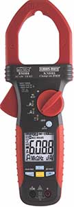
A natural development of this technique was a.c. clampmeters, which are now manufactured in a variety of different models & types. The basic principle is very simple; a current transformer whose single turn primary is formed by the lead carrying the current to be measured. The clamp jaws, which form the iron core of the transformer, carry the secondary winding. This winding drives an electronic circuit and in turn a digital display scaled as per the specifications of the meter.
The instrument is usually held and operated in one hand. The jaws are opened to clamp around the lead being measured by finger pressure on a ‘trigger’. A data hold button is provided to enable measurements to be made in a location where it is difficult to see the readings display. Range changing can be achieved by a thumb wheel switch or a rotary switch or a slide switch.
ACCURACY
It is the extent to which a given measurement agrees with the standard value.
eg. If the accuracy specified for the Range 0-20A with 3 ½ Digit Display is ± (1% rdg+5dgt) and the input is 15 A.
The display range is:
15 X 1 + 0.05 = 0.2
100
Max. Value = 15 + 0.2 = 15.20 A
Min. Value = 15 – 0.2 = 14.80 A
As with all measurements there are a number of variables which can affect the accuracy. The first effect to consider is, in common with all measurements, the effect that insertion of the meter has on the circuit. In this case, the reflected impedances are divided by the square of the turns ratio of the current transformer, the reflected impedance is very small and has a negligible effect.
The second effect to be considered is that of the position of the conductor being measured within the ring of the clamp-meter jaws. If the conductor is small in comparison to the jaws ring, the most accurate reading is obtained with the conductor at the centre. For a well designed clamp-meter, moving the conductor radially towards the edge of the ring has only a very small effect caused by leakage flux. This would have the greatest effect when the conductor is next to the jaws aperture.
The third effect is due to the gap between the jaws when closed. This is caused by the mating surfaces not being perfectly flat or dirt accumulated between the jaws surfaces. This causes leakage flux and hence poor coupling between the primary and secondary windings of the current transformer, which result in a reduced reading. But again, this loss is small as the jaw faces are ground to minimize the air gap at the opening point.
A fourth effect is caused by the presence of any a.c. magnetic field, such as those from large transformers or electric motors. Such magnetic fields would not have an affect but for the jaws gap. Alignment of the jaws with the magnetic fields will affect the error and hence, if possible, the clamp-meter should be rotated to keep this to a minimum, and be situated as far as possible away from sources of strong a.c. fields.
Another effect is caused by the iron magnetization. This is non-linear, particularly at the initial magnetisation stage when low level currents are being measured. At the other extreme, when large currents are to be measured, core saturation can occur. However, for the range specified, accuracy is not usually affected because due care is taken at the design stage.
Also, the frequency of the current being measured has an effect on the reading. Clampmeters are usually calibrated at the frequency at which they are to be used, such as
50 or 60Hz. Frequency has effects in several ways, for example, on leakage resistance, eddy currents and core saturation. The final effect which needs to be considered is ambient temperature. This will change the iron losses, jaw gap and circuit impedances; the temperature coefficient is often quoted.
DIFFERENT TYPES
There are a variety of types of clampmeters in the market. Some are very simple having current range only. Some models also have voltage measurement facility for voltages up to 1000V AC. With the development of sophisticated integrated circuits, more functions have been made available in digital clampmeters. The functions covered are DC Voltage, AC Voltage, Resistance, capacitance, frequency measurement etc. Almost all digital clampmeters have data hold facility that enables the reading to be held firm. Digital clampmeters have greater resolution & less ambiguity of reading.
One further type, know as leakage clampmeters, are capable of resolving current readings down to 1mA, and can be used for either single or three-phase supplies. For single-phase, if the meter is clamped around the live and neutral cables together, the meter will indicate the leakage current to earth. For three-phase work, operation is the same except that the meter is clamped around all three phase cables together. In this way the clampmeter will indicate current in the neutral cable and earth. If the neutral is also clamped, the resultant reading is the earth-leakage current. These can also be used to measure current at low levels in a single conductor.

High current d.c. measurement has also become practical with a clampmeter. This works on a very different principle. Since transformer action is not possible for d.c., a Hall Effect device is used to measure the magnetic flux in the clamp jaws. This is done by fitting the Hall Effect device in a gap in the magnetic circuit of the clampmeter. A reference current is applied across one plane of the device and potential is generated across the perpendicular plane. This output potential is proportional to the reference current and the magnetic flux level, which again is proportional to the current being measured. Hall effect devices work equally well with a.c. but then the output potential is also a.c. The output is measured, using a d.c. or a.c. voltmeter. All the possible errors discussed above also apply to this type of meter.
The Hall effect: if a current- carrying conductor is placed in a magnetic field (B) perpendicular to the direction of the current flow (I), a voltage (V) is induced across the conductor at right angles to both the magnetic field and the current flow. This voltage is proportional to both the magnetic field and conductor current. In a clamp-ammeter, the magnetic field is proportional to the current being measured. If the reference current is kept constant, the generated voltage is thus proportional to the current being measured.
ATTACHMENTS
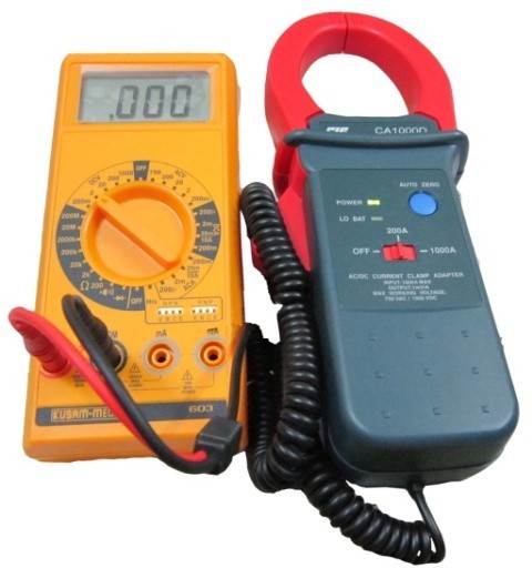
MODEL CA – 1000
Since most electrical engineers and electricians have either an analogue or digital multimeter, clamp-on attachments for these instruments have been developed. There are either a.c. only or combined a.c./d.c. types employing the principles already mentioned. In place of display these attachments are fitted with the output terminals for connecting to the multimeter.
Wattmeters must measure both current and voltage simultaneously. Obviously a similar principle to the clampmeter can be employed to measure the current. Voltage however is measured in the normal way using a pair of probes and a voltage divider. The information from the current and voltage measurements has to be processed to give a reading of power (VIcosØ).
Wattmeters uses electronic circuits to process the current and voltage measurements to give an indication of power. A phase sensitive detector can sense the in-phase component of voltage with respect to current and a multiplier is used to give the product of this component and the current. The output of the electronic processor can drive a digital display with the aid of an analogue-to-digital converter.
Another electronic method is to use a microprocessor to calculate cosØ from the sampled readings of voltage and current and then calculate the product VIcosØ. The output of the microprocessor is digital and can drive a digital display. Either of the electronic method can also be used to give a reading of the phase angle between the measured voltage and current.
SAFETY
A final point which must be considered concerns safety. When considering safety, it is normal to look for a relevant standard specification such as “UL” or “CE”. For clampmeters to conform to these specifications they should meet the requirements for double insulation and hence, as a rule of thumb, they should withstand a flash test of four times the working voltage, plus 2kV. This is twice the voltage required for single insulation.
Flash tests should be carried out between the jaws and the rest of the instrument wrapped in conductive foil. If there are any leads for voltage or resistance measurement, they should also withstand the flash test from themselves to the clampmeter body and to the jaws. If the working voltage or flash test voltage is quoted it should be for double insulation, and if not quoted, taken as the single insulation figure, for safety.
KUSAM-MECO Current Clamp – On Ammeters
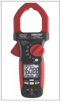
Useful Information concerning Current Clamp Meters and Clamp Adapters
KUSAM-MECO current clamp meters and clamp adapters are especially suited to measure AC and DC currents, in all instruments and systems, without interruption of the circuit.
Safety
All measuring instruments are manufactured in compliance with the specific safety regulations IEC61010 / EN 61010 which are the regulations pertinent to current clamps. Many models have ‘UL’ listing which is the highest safety.
Measuring Current without Interrupting Circuit
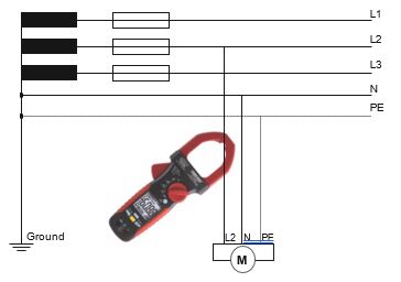
In practice it is not possible or safe to disconnect systems for the purpose of measuring the current flowing. Therefore, with the use of a Clamp Meter the current can be measured without any interruption whatsoever.
Instrument for use in conjunction with Clamp Meters – Main Adapters
Time consuming splitting of instrument feed lines can be avoided by using the KUSAM-MECO adapters in conjunction with a current clamp.
Simple Usage
KUSAM-MECO clamp meters and clamp adapters are easy to use. The conductor is completely surrounded by the current clamp. The measurement value appears on the digital display and can be read immediately.
Data Hold
All current clamps are equipped with a data hold feature. If the display is not directly readable during measurement, the value can be stored on the display by activating the data hold function.
Peak Hold
Some KUSAM-MECO clamps are equipped with a peak hold function, which can memorize the highest measurement value of the display. Therefore, the maximum current encountered during the test or monitoring time period can be recorded.
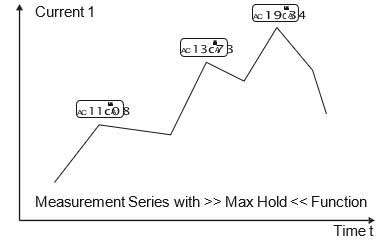
Display of Current clamp during activated max hold function
True RMS Measurement
More sophisticated circuitry is required for measuring the true RMS value of AC or DC currents with complex waveforms. The RMS value is important for all non-sinus shaped currents, e.g. phase-angle control. Generally, the measurement value displayed on conventional clamps is smaller than the actual measurement current present.
Please refer to >> useful Information concerning Multimeters << for further information about the RMS value.
Data Logger / RS232 – Interface
The KUSAM-MECO Power Clamp Meter 2709 has a RS232. This gives the possibility of recording over a long period.
This data can be transferred to a PC via the RS232 interface adapter. The measurement data can be processes via PC and displayed in table or graph form.
Clamp Adapter
KUSAM-MECO Clamp Adapters are ideally suited for applications where recording of measurement values is required. Depending on the type of circuit being evluated the primary current being measured can be converted to an essentially smaller, harmless secondary current or voltage. Application examples : control panel construction. Laboratory measurement circuits.
Leakage Current Measurement
High resolution mini current clamps for leakage currents from 10 mA indispensable for troubleshooting and testing of instruments at appliance test systems in compliance with DIN VDE 0701 / 0702 and BGV A2 (APPLIANCE TESTER).
Leakage currents which do not return via an electrical conductor (e.g. N, PE) can be quickly, safely and easily measured by surrounding all active conductors (e.g. L1, L2, L3, N or L1, N). The normal measurement method considers only leakage currents in N or PE and, therefore, can only be considered as replacement, measurement, not comprising all currents.
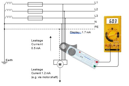
Harmonic Wave Measurement Clamp
At any location, loads such as motors, computers and rectifiers, “bend” the voltage or current. As a result so-called harmonic waves are generated.
These represent additional frequencies, being even multiples of the basic wave of the 50Hz current mains.
Most frequently occurring is the odd multiple of the basic wave, being the third, the fifth, the seventh etc. in many cases, the mains voltage distortion is not recognised by the load, as no direct consequences are generated by the harmonics. Depending on the amplitude of the harmonics present, excessive voltage may be generated and lead to overheating, in particular in the case of inductive loads (motors, transformers, etc.) They in turn, may destroy any loads subsequently connected.
The digital Harmonic Wave Power Meter, 2746 clamp an universally applicable measurement instrument.
Apart from standard measurement functions, such as current, voltage, and resistance, the clamp can measure harmonic waves up to the 20th harmonics.
The smallest current or current overlapping can thus be measured and assigned.
The instrument is built in compliance with the most recent versions of EN61010, IEC61010, DIN VDE 0411 and ensures safe and reliable performance.
The current clamp is the ideal support for testing and measuring harmonic waves and is used for installations and service applications.


