In the TME catalogue, you can find more than 1300 tantalum and tantalum-polymer capacitors from KYOCERA AVX, including 434 SMD tantalum-polymer capacitors and 874 tantalum capacitors (150 THT and 724 SMD components). Their operating voltage varies between 2 V DC and 125 V DC, while their capacitance can be anything from 0.1 µF to 1500 µF. Thanks to their unique features, tantalum capacitors can be used in many applications and in certain cases as aluminum electrolytic or MLCC replacements. In this article, we will describe their design, construction, advantages and disadvantages, along with indicating the issues to look out for when deciding to use them.
- Design, construction and the production process of capacitors
- SMD capacitors – dimensions and specification
- THT capacitors – dimensions and specification
- Advantages and disadvantages
Design and construction of tantalum capacitors
Manufacturing capacitors is a complicated process in which the parameters for each production stage need to be chosen and set with utmost precision. In this article, we present such a process according to the Kyocera-AVX specifications.
Anode
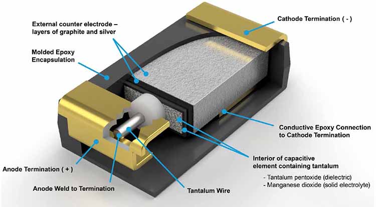
The design of tantalum capacitors is based on the structure of tantalum, which looks a lot like a sponge. Such a structure contains an anode, a cathode and a dielectric. The manufacturing process of this type of capacitor begins with compressing tantalum powder around a tantalum wire and sintering it at high temperature, to create the anode. The application of high temperature results in powder particles connecting with one another (hence the structure), but in order to attain a specific set of parameters, suitable temperature and sintering time need to be carefully defined. If the sintering time is too long or its temperature is too high, the capacitor’s capacitance will be lower. Conversely, if the sintering time is too short or its temperature is too low, the resulting capacitance will be higher. This in fact means that the capacitor’s parameters (capacitance and operating voltage) are determined as early when selecting the powder. It is also important to remember that the size (micrometer-order) and shape of powder particles will have an effect on many production stages.

Manufacturer’s materials
The following formula describes capacitance in tantalum capacitors:
ε – dielectric permittivity
ε0 – vacuum permittivity
A – dielectric surface area
d – dielectric layer thickness
Dielectric
The dielectric is at the heart of every capacitor, as it ‘traps’ energy in its electric field. In tantalum capacitors, tantalum oxide (Ta2O5) is created as the dielectric. As mentioned above, after sintering, the stage of forming the dielectric layer begins. Tantalum is a conductor itself, so it can’t be used as a dielectric. That is why the components undergo the process of anodizing, i.e. they are submerged into an acid solution heated to 85°C, and subjected to electrical current which leads to a chemical reaction forming Ta2O5 Tantalum pentoxide on the surface of the anode. The thickness of the dielectric layer is determined by voltage, so the current is initially maintained on a constant level until the desired voltage is reached. The voltage is then kept at this level until a uniform thickness of the dielectric layer is attained on the entire component surface. Tantalum capacitators are polarized due to reactions which take place during the forming of the dielectric layer, as the layer of oxide, which acts as a semiconductor, forms between tantalum oxide and pure tantalum. The dielectric layer is formed at a voltage higher than the operating voltage of the capacitor. Depending on the series, this voltage can be 2 to 4 times higher than what the capacitor is supposed to work at.
Cathode
The next stage of production involves forming the cathode as a result of pyrolysis of manganese (II) nitrate into manganese (IV) oxide. It is done by submerging the components into an aqueous solution of manganese (II) nitrate and heat-treating them to remove water. The process is repeated several times to ensure that the cathode is sufficiently thick. After that, the components are covered with graphite and, in the end, with silver. Graphite is necessary to separate silver and manganese oxide, which would otherwise react and negatively impact the characteristics of the component. Alternatively, polymer can be used as a substitute of manganese in the process of forming the cathode, which has a number of advantages, but is not free from disadvantages.
SMD tantalum and tantalum-polymer capacitors
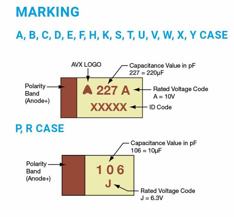
SMD capacitors are the most common type of tantalum capacitors. SMD tantalum capacitors are a close match to the standard MLCC case sizes, thanks to which MLCCs could be replaced with tantalum capacitors without the need to change the PCB footprint. In the case of tantalum capacitors, not only length and width are indicated in terms of dimensions (as in MLCCs) but also height. That is why each dimension has a Latin letter attributed to it. What’s more, voltage, capacitance and polarization of the capacitor are also stated on the housing. Below, you can find out about the markings and dimensions.
| HOUSING | IMPERIAL EIA | METRIC EIA | LENGTH | WIDTH | HEIGHT |
| A | 1206 | 3216-18 | 3.2 mm / 0.126″ | 1.6 mm / 0.063″ | 1.6 mm / 0.063″ |
| B | 1210 | 3528-21 | 3.5 mm / 0.138″ | 2.8 mm / 0.11″ | 1,9 mm / 0.075″ |
| C | 2312 | 6032-28 | 6 mm / 0.236″ | 3.2 mm / 0.126″ | 2.6 mm / 0.102″ |
| D | 2917 | 7343-31 | 7.3 mm / 0.287″ | 4.3 mm / 0.169″ | 2.9 mm / 0.114″ |
| E | 2917 | 7343-43 | 7.3 mm / 0.287″ | 4.3 mm / 0.169″ | 4.1 mm / 0.162″ |
| U | 2924 | 7361-43 | 7.3 mm / 0.287″ | 6.1 mm / 0.24″ | 4.1 mm / 0.162″ |
| V | 2924 | 7361-38 | 7.3 mm / 0.287″ | 6.1 mm / 0.24″ | 3.55 mm / 0.14″ |
| MARKINGS FOR LOW-PROFILE CAPACITORS | |||||
| F | 2312 | 6032-20 | 6 mm / 0.236″ | 3.2 mm / 0.126″ | 2 mm / 0.079″ |
| H | 1210 | 3528-15 | 3.2 mm / 0.126″ | 2.8 mm / 0.11″ | 1.5 mm / 0.059″ |
| K | 1206 | 3216-10 | 3.2 mm / 0.126″ | 1.6 mm / 0.063″ | 1 mm / 0.039″ |
| P | 0805 | 2012-15 | 2.05 mm / 0.081″ | 1.35 mm / 0.053″ | 1.5 mm / 0.059″ |
| R | 0805 | 2012-12 | 2.05 mm / 0.081″ | 1.3 mm / 0.051″ | 1.2 mm / 0.047″ |
| S | 1206 | 3216-12 | 3.2 mm / 0.126″ | 1.6 mm / 0.063″ | 1.2 mm / 0.047″ |
| T | 1210 | 3528-12 | 3.2 mm / 0.126″ | 2.8 mm / 0.11″ | 1.2 mm / 0.047″ |
| W | 2312 | 6032-15 | 6 mm / 0.236″ | 3.2 mm / 0.126″ | 1.5 mm / 0.059″ |
| X | 2917 | 7343-15 | 7.3 mm / 0.287″ | 4.3 mm / 0.169″ | 1.5 mm / 0.059″ |
| Y | 2917 | 7343-20 | 7.3 mm / 0.287″ | 4.3 mm / 0.169″ | 2 mm / 0.079″ |
From the AVX documentation
As mentioned previously, the capacitor’s parameters can be found on its housing. Below, we present a list of markings used in the KYOCERA-AVX TAJ series for various housings.

Manufacturer’s materials
THT tantalum capacitors
Tantalum capacitors with leads for THT mounting are also available from TME. They differ from the SMD variant only in terms of the last stage of production, during which wire leads are attached to capacitors. For the THT tantalum capacitors’ parameters, there is a standard outline of markings on the housing too;
| LEADS | C, F, G, H | B, S, D | |
| HOUSING | H | *H1 | DIAMETER |
| A | 8.5 mm / 0.33″ | 7 mm / 0.28″ | 4.5 mm / 0.18″ |
| B | 9 mm / 0.35″ | 7.5 mm / 0.3″ | 4.5 mm / 0.18″ |
| C | 10 mm / 0.39″ | 8.5 mm / 0.33″ | 5 mm / 0.2″ |
| D | 10.5 mm / 0.41″ | 9 mm / 0.35″ | 5 mm / 0.2″ |
| E | 10.5 mm / 0.41″ | 9 mm / 0.35″ | 5.5 mm / 0.22″ |
| F | 11.5 mm / 0.45″ | 10 mm / 0.39″ | 6 mm / 0.24″ |
| G | 11.5 mm / 0.45″ | 10 mm / 0.39″ | 6.5 mm / 0.26″ |
| H | 12 mm / 0.47″ | 10.5 mm / 0.41″ | 7 mm / 0.28″ |
| J | 13 mm / 0.51″ | 11.5 mm / 0,45″ | 8 mm / 0.31″ |
| K | 14 mm / 0.55″ | 12.5 mm / 0.49″ | 8.5 mm / 0.33″ |
| L | 14 mm / 0.55″ | 12.5 mm / 0.49″ | 9 mm / 0.35″ |
| M | 14.5 mm / 0.57″ | 13 mm / 0.51″ | 9 mm / 0.35″ |
| N | 16 mm / 0.63″ | 9 mm / 0.35″ | |
| P | 17 mm / 0.67″ | 10 mm / 0.39″ | |
| R | 18.5 mm / 0.73″ | 10 mm / 0.39″ |
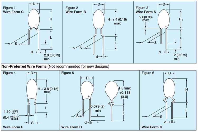
Below, we present the types of lead forms and the housings that are compatible with them.

Manufacturer’s materials
| LEAD FORM | FIGURE | HOUSING SIZE | LEAD LENGTH (L) | LEAD SPACING (S) | LEAD DIAMETER (D) |
| C | Figure 1 | A – R | 16.00±4.00 mm (0.630″±0.160″) | 5.00 mm±1.00 mm (0.200″±0.040″) | 0.50 mm±0.05 mm (0.020″±0.002″) |
| B | Figure 2 | A – J | 16.00±4.00 mm (0.630″±0.160″) | 5.00 mm±1.00 mm (0.200″±0.040″) | 0.50 mm±0.05 mm (0.020″±0.002″) |
| S | Figure 3 | A – J | 16.00±4.00 mm (0.630″±0.160″) | 2.50 mm±0.50 mm (0.100″±0.020″) | 0.50 mm±0.05 mm (0.020″±0.002″) |
| F | Figure 4 | A – R | 3.90±0.75 mm (0.155″±0.030″) | 5.00 mm±1.00 mm (0.200″±0.040″) | 0.50 mm±0.05 mm (0.020″±0.002″) |
| D | Figure 5 | A – H | 16.00±4.00 mm (0.630″±0.160″) | 2.50 mm±0.50 mm (0.100″±0.020″) | 0.50 mm±0.05 mm (0.020″±0.002″) |
| G | Figure 6 | A – J | 16.00±4.00 mm (0.630″±0.160″) | 3.18 mm±0.50 mm (0.125″±0.020″) | 0.50 mm±0.05 mm (0.020″±0.002″) |
| H | Similar to Figure 1 | A – R | 16.00±4.00 mm (0.630″±0.160″) | 6.35 mm±1.00 mm (0.250″±0.040″) | 0.50 mm±0.05 mm (0.020″±0.002″) |
Advantages of tantalum capacitors
Tantalum capacitors boast a great number of advantages, and thus can be used in many different applications and they can also be used to replace or support aluminum electrolytic capacitors and MLCCs, which would save space on PCB’s. One of the most essential features of tantalum capacitors is their stability of parameters over a wide range of temperatures – capacitance is stable in temperature range from -55°C to 125°C. Another advantage is the lack of “DC bias” – unlike MLCCs, tantalum capacitors don’t lose their capacitance when DC voltage appears in the signal line. Additionally, tantalum capacitors easily maintain a service life that is as long as that of ceramic capacitors. Regarding lifetime, tantalum capacitors have another advantage over MLCCs, which is lack of the aging effect (visible in Class 2 MLCCs), meaning the loss of capacitance over time. Tantalum capacitors do not age, so they retain their parameters for many years. Also, thanks to their spongy structure, tantalum capacitors feature high volumetric efficiency. For instance, standard SMD aluminum electrolytic capacitors have the volumetric efficiency of 11.8 µFV/mm3, whereas tantalum capacitors reach the efficiency of 63 µFV/mm3 and above. This means tantalum capacitors can achieve several times higher capacitance in comparison to aluminum electrolytic capacitors for a given size. When it comes to tantalum-polymer capacitors, they have low ESR, i.e. equivalent series resistance, which can offer higher efficiency and ripple current rating of the capacitor while operating. This is the reason why tantalum-polymer capacitors are perfect for applications such as medical equipment, IOT, DC/DC converters and smart metering. The lower ESR that Polymer can provide may allow a smaller chip to be used within a design, beneficial to space limited applications such as wearables, IOT, signal processing applications amongst others.
Disadvantages of tantalum capacitors
Unfortunately, tantalum capacitors also have a few disadvantages, due to which they are not suitable for every application. For instance derating, i.e. needing to select a lower operating voltage than the rated voltage of the component. In the case of tantalum capacitors, it can be as high as 70%, which means that a capacitor rated for 35V should operate at 12V, when high current in low impedance circuits or rapid voltage spikes are present. Therefore, the actual operating voltage is lowered, so that the capacitor maintain its reliability. It should be noted that in most cases applications are ok to work with 50% voltage derating. Additional derating could be applied due to higher (above 85°C) operating temperature. Note that tantalum capacitors are at risk of failing if exposed to overcurrent or voltage spikes, but also due to inappropriate mounting. Tantalum capacitors cannot be mounted in any desired way, as they have a defined polarization, and failure to comply with it when mounting the capacitor would cause issues. To avoid it, pay attention to the polarization markings and mounting (reflow) conditions. Another issue with tantalum capacitors is the way they fail – as a result of an avalanche breakdown, a short-circuit occurs. Tantalum-polymer capacitors are less exposed to this issue, due to their low ESR and lack of inrush current sensitivity. However, a problem that becomes apparent in tantalum-polymer capacitors is their sensitivity to moisture, which is at the MSL 3 level or higher for specific parts, some reach MSL 5. Therefore, it is required to control the conditions of their storage as well as the conditions under which the capacitors are mounted and operate. The last disadvantage of tantalum capacitors is their rather low operating voltage – in the case of MLCCs and aluminum electrolytic capacitors, the voltage can reach hundreds of V or even kV, whereas tantalum capacitors can only operate at the max. voltage of 125 V.
Summary
With thoughtful circuit design and careful selection of tantalum capacitor devices, their advantages greatly overshadow their disadvantages. They have been used for decades in a wide variety of applications from commercial handheld devices to high reliability space missions. Tantalum capacitors offer large values of capacitance and power handling in a small volume for size/weight constrained designs. They are also superior when capacitance value stability over a long period of time across a wide range of temperatures and circuit conditions is needed. As discussed previously, they arrive in multiple packages and cathode options with a wide range of parameters that are optimal for many applications.


