1 About IGBT
IGBT (Insulated Gate Bipolar Transistor) is a kind of power semiconductor. It can be simply considered as a fast switch which can be used to control on/off of a high voltage signal by a low voltage pulse. It has three electrodes: gate, collector, emitter. The low voltage pulse is applied between gate and emitter, and the high voltage signal is applied across collector and emitter, as figure 1 shows.

With Darlington structure combining of BJT (Bipolar Junction Transistor) and MOSFET, IGBT has the advantages of both, like voltage controlling, low driving power, low saturation voltage, high withstand voltage, as figure 2 shows.
2 Applications of IGBT
IGBT is broadly used in all kinds of applications such as strong electric field, new energy automotive, power inverter, telecommunication, computer, consumer electronics, aerospace, new energy, etc. Figure 3 shows some typical applications.

In figure 4 below, we can see a typical simplified schematic of power converter circuit (or voltage frequency drive) which is generally used in motor drive. The three-phase AC line input is rectified by a six-pulse rectifier to a stable DC voltage which then goes to the DC-AC power inverter circuit. The output is a three-phase pulse-modulated signal managed by control logic/system module. Six IGBTs are used in this typical power converter circuit to generate a proper signal with desired speed, power, efficiency etc.

3 Dynamic characteristics verification of IGBT
It’s critical to get accurate dynamic characteristics of IGBTs due to its impact on the performance of the circuit.
As more new players nowadays involve in designing and manufacturing of IGBTs, the verification of reliability and qualification is getting more necessary. It brings the increasing demand of tests of IGBTs in different phases of designing and manufacturing.
Moreover, IGBT materials are transitioning from silicon to wide bandgap semiconductors such as silicon carbide (SiC) and gallium nitride (GaN) due to their superior performance in automotive and industrial applications. It brings more challenges like minimizing switch losses, reducing the impact of reversed recovery current. These designs must be rigorously measured to ensure compliance.
DPT (Double Pulse Test) Technology has been the industry standard method for measuring the dynamic characteristics of IGBTs.
As figure 5 shows, the double-pulse signal is applied between gate and emitter to control on/off of the IGBT under test. The PicoScope model shows in the simplified testing diagram is PicoScope 6824E which is an oscilloscope with 8 analog channels and built-in FG/AWG as well as flexible resolution (8 bits to 12 bits). We can generate a double-pulse waveform with the AWG in PicoScope by loading the edited data files accordingly or with an external signal source.
A passive probe, a high voltage differential probe and a current probe are required to acquire the double-pulse waveform, Vce (voltage signal), Ic (current signal).

Dynamic characteristics parameters of IGBT are mainly relevant to turn-on/off characteristics parameters and reverse recovery characteristics parameters. Some typical parameters and waveforms addressed below are from IEC 60747-9-2019.
Turn-on times (td(on), tr, ton) and turn-on energy (Eon):

Turn-off times (td(off), tf, toff, tz) and turn-off energy (Eoff):

Peak reverse recovery current (Irrm), reverse recovery time (trr), reverse
recovery energy (Err) and reverse recovered charge (Qrr) of a reverse-blocking
IGBT:

4 Challenges to test dynamic characteristics parameters of IGBT
High reliability is always one of the important factors for an ATE system which is usually used in the manufacture lines that always need to run continuously day and night.
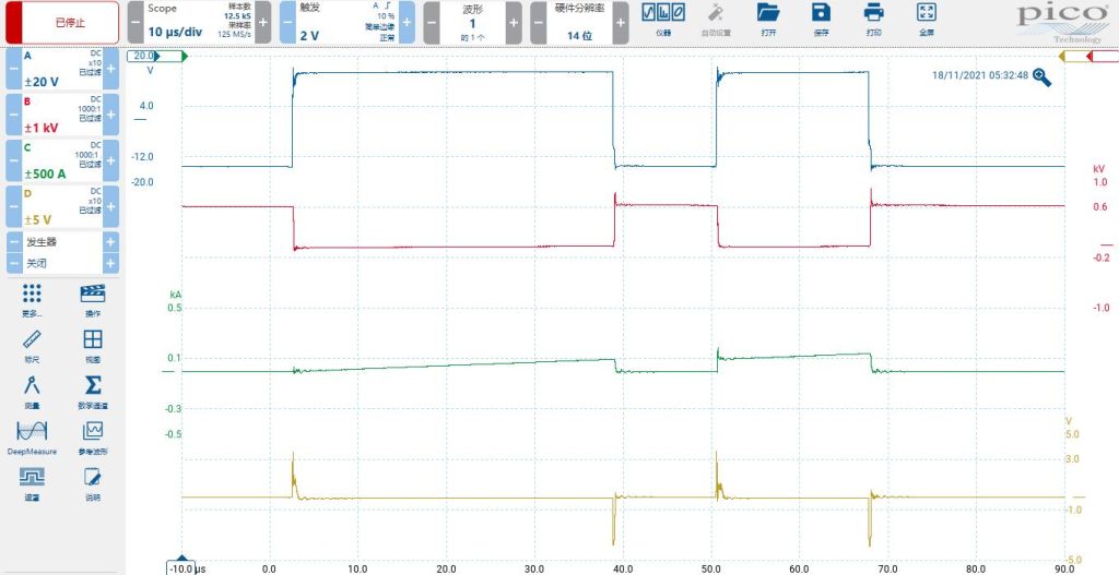
Equally important is high accuracy. As the figure 9 and 10 below show, the voltage peaks in Vce due to the stray inductance and the current peaks in Ic due to the diode reverse recovery are high frequency pulses with narrow width. To capture and measure such kind of fast pulses accurately needs the instrument to have both high ADC resolution and high sampling rate.

Figure 10 below shows the real IGBT waveforms of Double Pulse, Vce, Ic, Ig tested by PicoScope 5444D.

Cost-efficiency, compact size, fast measurement speed are also getting critical due to the fierce competition in the market besides high reliability and accuracy.
It’s a big challenge for a data acquisition instrument to meet all the above demands.
5 Why PicoScopes?

Several kinds of PicoScope models like PicoScope 5444D, PicoScope 6404E, PicoScope 6824E are popularly used in automated testing systems for IGBTs in terms of different requirements for discrete IGBTs, modular IGBTs in different technologies.

Figure 12 shows an automated testing system for IGBTs with PicoScope 6404E integrated. An industrial PC and a high voltage power supply as well as many accessories are also used in this equipment in addition to PicoScope 6404E. The customer develops their own application software in programming languages of LabVIEW and Python based on Pico SDK.
The main reasons that people like to integrate PicoScopes into their automated testing systems for IGBTs are the unique advantages and powerful capabilities of PicoScopes.
- High reliability
Established in 1991, Pico Technology has been focusing on the development and manufacture of PC-based test instrument and data acquisition equipment. Decades of product iteration and stringent quality controls make PicoScopes highly reliable.
- Cost-efficiency
Different from benchtop instruments, the fact that PicoScopes don’t have PC in the box gives them more unique hardware advantages due to the simple structure, including high bandwidth/sampling rate, deep memory, high/flexible ADC resolution, multiple analog and digital inputs, fast speed, etc. The use of full capability of an external PC allows PicoScopes more software capabilities, including 30+ serial decoders, advanced math functions (FFT, filters, measurements plotting, etc). Moreover, dozens of PicoScope models make the customers easier to pick one affordable and suitable for their applications.
- High/Flexible ADC resolution
PicoScopes offer a wide range of vertical resolution options from 8 to 16 bits. The higher the resolution, the greater the vertical accuracy and the dynamic range. The flexible resolution feature in PicoScopes is based on Pico’s breakthrough ADC technology which allows users to switch from 8 to 16 bits in one unit.
- Fast and powerful SDK
PicoScopes provide a level of interconnectivity and customization that is not usually available on most benchtop oscilloscopes. The SDK (Software Development Kit) allows users to create custom applications for their particular projects. That makes PicoScopes go beyond just being a regular oscilloscope. PicoScopes running under SDK have much better performance. For example, it can acquire and transmit data continuously to PC with the speed up to 312 MS/s; The memory can be segmented up to 2 million; The users can set the advanced triggers and generate waveforms programmatically. Programming with SDK is simple and easy. Professional technical support is always ready and lots of code examples can be found in github.com/picotech.
All Pico products including PicoScopes come with a free-of-charge SDK. The SDK includes drivers for Windows, macOS, Linux and Raspberry Pi (ARM7). It allows users to write their own software to control the instruments with popular languages such as C, C#, C++, Python, MATLAB, LabVIEW and Microsoft Excel.
- Compact and portable units
Unlike traditional benchtop instruments, PicoScopes are compact, light and portable. When used with a laptop computer, a PicoScope allows you to carry a complete electronics toolset in one bag with your PC. And small size also makes PicoScopes easier to be integrated into the systems with almost no increase in weight or size.


