Electronics Era

  • About Us
  • Advertise with Us
  • Contact Us
  • e-Mag
  • Webinars
Header logo on website
Advertisement
Advertisement
Menu
  • News
    • Industry News
    • Product News
  • TECH ROOM
    • Sensor
    • VR / AR
    • Embedded
    • Medical Electronics
    • Industry 4.0
    • Robotic
    • Automation
    • Smart Machine
    • Component
    • Manufacturing
    • Aerospace & Defence
    • Security
    • Policy
  • Semiconductor
    • AUTOMOTIVE ELECTRONICS
      • EVs
      • HEVs
      • ADAS
      • Connected Cars
    • IoT-Internet of Things
      • Development Kit
      • IoT Design
    • Power Electronics
      • AC-DC/DC-DC Converters
      • Mosfets
      • IGBTs
      • LEDs
  • T & M
    • 5G testing
    • Oscilloscopes
    • SDN & NFV
    • RF & Wireless
  • AI/ML
  • Telecom
    • 5G/6G
  • RENEWABLES
    • Sustainability
  • Future Tech
    • Data Center
    • Cloud Computing
    • Big Data Analytics
  • Webinars
  • Editor’s Pick
    • Tech Article
    • Tech Blog
    • White Papers
    • EE-Tech Talk
    • Market Research
  • EE Awards
    • EE Awards 2025
    • EE Awards 2024
  • MORE
    • E-Mag
    • Events
    • Subscription
    • Contact Us
Home TECH ROOM Embedded

Würth Elektronik Defines an Electrical Property for Molded Inductors

New Testing Procedure for Determining Dielectric Strength

Nimish by Nimish
July 18, 2024
in Embedded, Product News
Reading Time: 3 mins read
Würth Elektronik

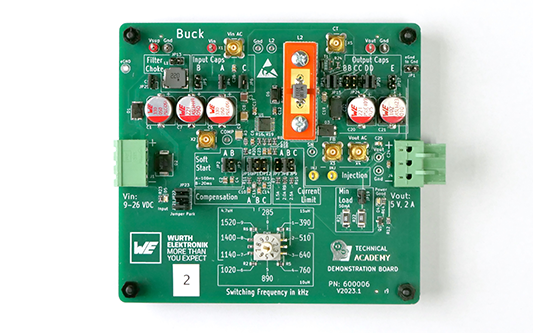
Example application: DC/DC converter

Share on FacebookShare on TwitterShare on LinkedIn

Waldenburg (Germany) – Würth Elektronik has developed a new testing procedure for determining the maximum operating voltage of molded inductors. The manufacturer of electronic and electromechanical components introduces developers to the electrical property of dielectric strength and what happens if it is exceeded in an application which is described in Application Note 126 (www.we-online.com/ANP126). The molded inductors from the Power Magnetics product portfolio (e. g., WE-MAPI, WE-XHMI, WE-LHMI) are now successively supplemented with the value of the maximum operating voltage Vop as a new parameter in the specifications.

Based on the new testing procedure, Würth Elektronik defines the maximum operating voltage Vop in its data sheets. This represents the voltage at which an inductor can be operated continuously in the application without impairing performance, risking damage or overheating the inductor. The operating voltage is therefore a limit value for the input voltage, up to which the inductor can be used reliably in an application without irreversible damage.

The test concept examines the behavior of inductors up to their voltage limits under realistic conditions in a DC-DC full-bridge converter (voltage transients of up to 60 V/ns and frequencies of up to 2 MHz). The approximate voltage limit is firstly evaluated using a short-term test. The operating voltage is then defined on this basis and verified in a long-term test.

The new product characteristic in the data sheet clearly indicates the maximum operating voltage of the inductor in the application.
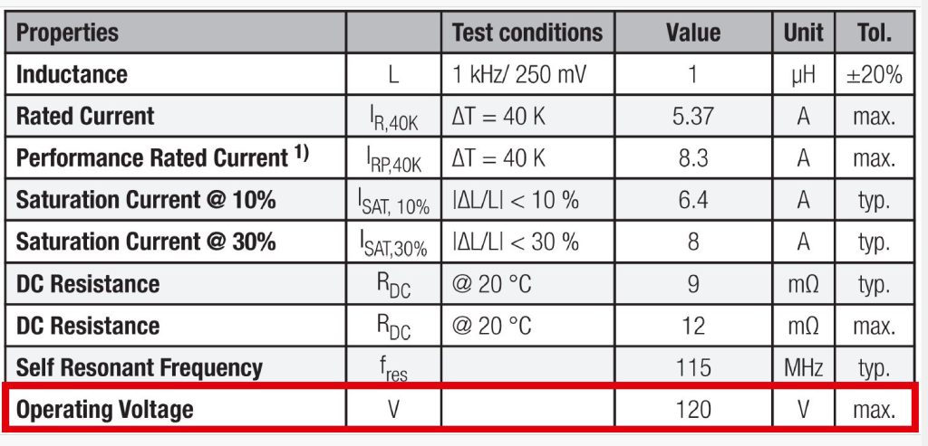
The new product characteristic in the data sheet clearly indicates the maximum operating voltage of the inductor in the application.

Background

Thanks to steady technological advancement in the semiconductor industry, today’s MOSFETs can now achieve high current densities and short switching times. For this reason, the question of the dielectric strength of coils has become increasingly important in recent years when it comes to selecting the appropriate inductor.

What’s more: Continuous optimization of the production process and the material composition of molded inductors enable high permeability of the ferrite material to achieve the highest possible inductance values in the smallest possible package space. The power density per volume can therefore be raised continuously.

This entailed a steady increase in the proportion of iron powder or iron alloys relative to the insulation of the binder, resulting in the distance between individual grains becoming progressively smaller. If the insulation barrier between the individual metal particles is not high enough for the voltage applied in the application, a conductive path is created through the core material, caused by arcing between the individual metal particles. It may be observed in the application that the profile of the ripple current changes. Schematically, there is now a resistor parallel to the inductor.

The consequences: Self-heating of the coil rises dramatically due to the rising losses. These additional losses considerably reduce the inductor’s efficiency. The advantage of a DC/DC converter – to transmit voltage levels with high efficiency – is lost.

Tags: electromechanical componentsWürth ElektroniK
Nimish

Nimish

Join Our Newsletter

* indicates required
Electronics Era

Electronics Era, India's no.1 growing B2B news forum on Electronics and Cutting Edge Technology is exploring the editorial opportunity for organizations working in the Electronics Manufacturing Services(EMS) Industry.

Follow Us

Browse by Category

  • 5G testing
  • 5G/6G
  • AC-DC/DC-DC Converters
  • ADAS
  • Aerospace & Defence
  • AI/ML
  • Automation
  • AUTOMOTIVE ELECTRONICS
  • Big Data Analytics
  • Blockchain
  • Cloud Computing
  • Component
  • Connected Cars
  • Data Center
  • Editor's Desk
  • EE-Tech Talk
  • Electronics Components
  • Embedded
  • EVs
  • Future Tech
  • HEVs
  • Industry 4.0
  • Industry News
  • IoT-Internet of Things
  • LED & Lighting
  • LEDs
  • Manufacturing
  • Market Research
  • Medical Electronics
  • Mosfets
  • News
  • Oscilloscopes
  • Policy
  • Power Electronics
  • Product News
  • RENEWABLES
  • RF & Wireless
  • Robotic
  • SDN & NFV
  • Security
  • Semiconductor
  • Sensor
  • Smart Machine
  • SMT/PCB/EMS
  • Sustainability
  • T & M
  • Tech Article
  • Tech Blog
  • TECH ROOM
  • Telecom
  • Uncategorized
  • VR / AR
  • White Papers

Recent News

Telecom

World Telecom Day Being Commemorated on 17th May with this year’s theme ‘Gender Equality in Digital Transformation’.

May 17, 2025
Advances On Manufacturing And Next Generation Devices

Advances On Manufacturing And Next Generation Devices

May 16, 2025
  • About Us
  • Advertise with Us
  • Contact Us

© 2022-23 TechZone Print Media | All Rights Reserved

No Result
View All Result
  • News
    • Industry News
    • Product News
  • TECH ROOM
    • Sensor
    • VR / AR
    • Embedded
    • Medical Electronics
    • Industry 4.0
    • Robotic
    • Automation
    • Smart Machine
    • Component
    • Manufacturing
    • Aerospace & Defence
    • Security
    • Policy
  • Semiconductor
    • AUTOMOTIVE ELECTRONICS
      • EVs
      • HEVs
      • ADAS
      • Connected Cars
    • IoT-Internet of Things
      • Development Kit
      • IoT Design
    • Power Electronics
      • AC-DC/DC-DC Converters
      • Mosfets
      • IGBTs
      • LEDs
  • T & M
    • 5G testing
    • Oscilloscopes
    • SDN & NFV
    • RF & Wireless
  • AI/ML
  • Telecom
    • 5G/6G
  • RENEWABLES
    • Sustainability
  • Future Tech
    • Data Center
    • Cloud Computing
    • Big Data Analytics
  • Webinars
  • Editor’s Pick
    • Tech Article
    • Tech Blog
    • White Papers
    • EE-Tech Talk
    • Market Research
  • EE Awards
    • EE Awards 2025
    • EE Awards 2024
  • MORE
    • E-Mag
    • Events
    • Subscription
    • Contact Us

© 2022-23 TechZone Print Media | All Rights Reserved

Advertisement
Advertisement