About the Author : Anne Mahaffey joined Analog Devices in 2003 as a test engineer supporting direct digital synthesis products after receiving her B.S.E.E. from the Georgia Institute of Technology and her M.S.E.E. from North Carolina State University. She spent over 10 years architecting and supporting design tools in the Precision Studio tool suite and now supports LTspice® as a principal applications engineer.
Abstract
Voltage and current sources in LTspice® offer simple ways to create pulses and sinusoidal waveforms. But, if something more complex and arbitrary is needed, a piecewise linear (PWL) function may be used to create a waveform using straight-line segments defined by time/value points.

Introduction
Piecewise linear (PWL) functions are a series of straight-line segments that can be used to create a voltage or current waveform in LTspice®. PWL segments are defined as time/value pairs and are one of the many ways to define a voltage or current waveform for transient simulations.
Adding a PWL Function to a Voltage or Current Source
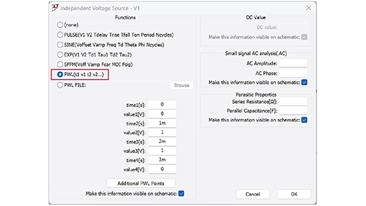
To add a PWL function to a newly placed voltage or current source, right-click on the voltage or current source symbol in the schematic. Next, click Advanced to view all settings, and select PWL(t1 v1 t2 v2…) in the Functions section.
Defining a PWL Waveform
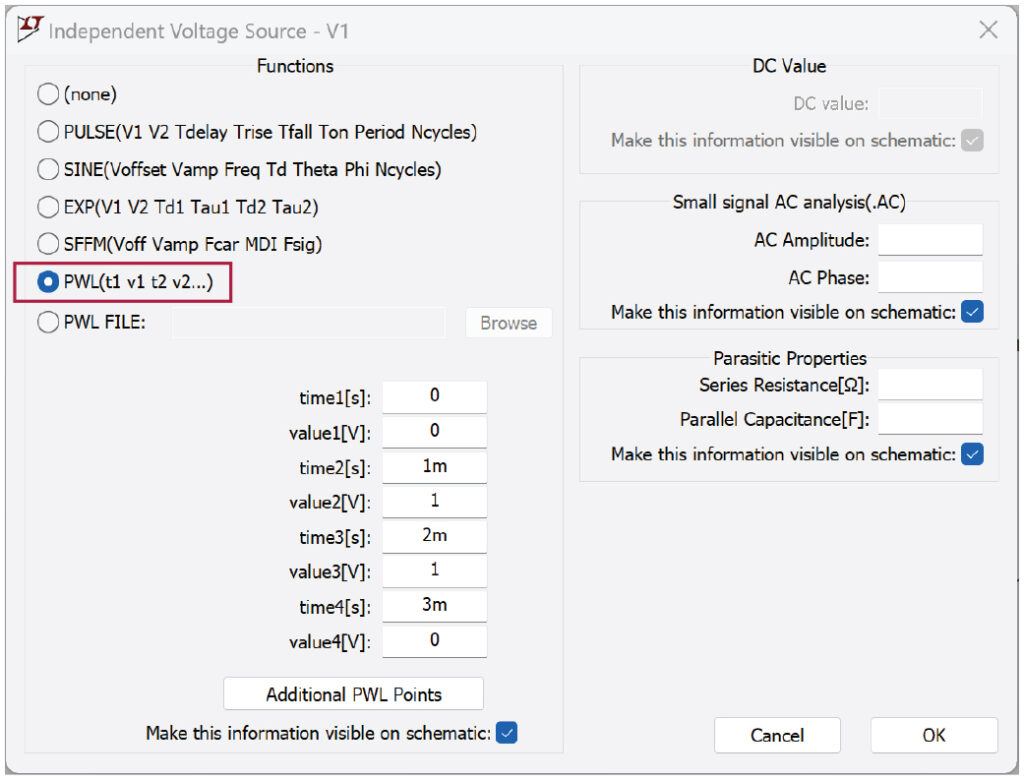
After selecting PWL(t1 v1 t2 v2…), enter time/value pairs into the input fields (only enter as many as you need). Click Additional PWL Points if you need more than four points. Click OK when done.
A PWL statement will be constructed using the values entered in the Advanced setting dialog:
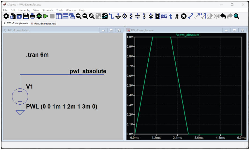
PWL (0 0 1m 1 2m 1 3m 0)
Figure 1 and Figure 2 show an example with four point pairs with the PWL function syntax.

PWL-Examples.asc is an LTspice schematic file that contains this and other examples in this article.
Using Relative Time Values in a PWL Waveform
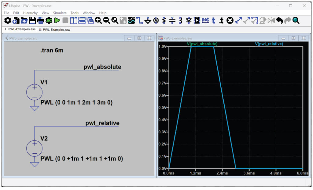
Time values can also be defined relative to the previous time point by prefixing the time with a + sign.
PWL (0 0 +1m 1 +1m 1 +1m 0)
Figure 3 shows both absolute and relative times that result in identical waveforms.
Defining a Repeating PWL Waveform
LTspice allows edits of time/value pairs in the Advanced dialog. To explore other syntax elements of PWL, right-click on the PWL statement in the schematic to edit further. To create a repeating PWL waveform, add REPEAT and ENDREPEAT to the PWL statement.
To repeat the example waveform in Figure 3 for a fixed number of cycles, use REPEAT FOR X:
PWL REPEAT FOR 5 (0 0 1m 1 2m 1 3m 0) ENDREPEAT
To repeat the example waveform in Figure 3 indefinitely, use REPEAT FOREVER:
PWL REPEAT FOREVER (0 0 1m 1 2m 1 3m 0) ENDREPEAT
Figure 4 shows the original PWL example, along with a version of that waveform that repeats five times, as well as a waveform that repeats indefinitely (create multiple plot panes by right-clicking on the waveform viewer and select Add Plot Pane Above/Below).
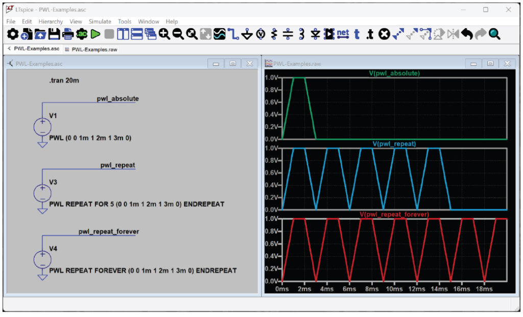
Figure 4. PWL waveforms constructed with REPEAT FOR and REPEAT FOREVER parameters.
Using a Trigger to Start a PWL Sequence
Figure 5 shows an example of a PWL waveform that depends on a trigger condition. In this example, the waveform sequence begins when the trigger expression (V(trig) > 1) is true. The waveform is disabled when the expression is false.
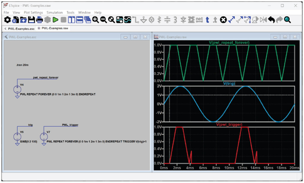
For this example, the waveform repeats while the trigger condition is true:
PWL REPEAT FOREVER (0 0 1m 1 2m 1 3m 0) ENDREPEAT TRIGGER V(trig)>1
Stretching or Shrinking a PWL Waveform
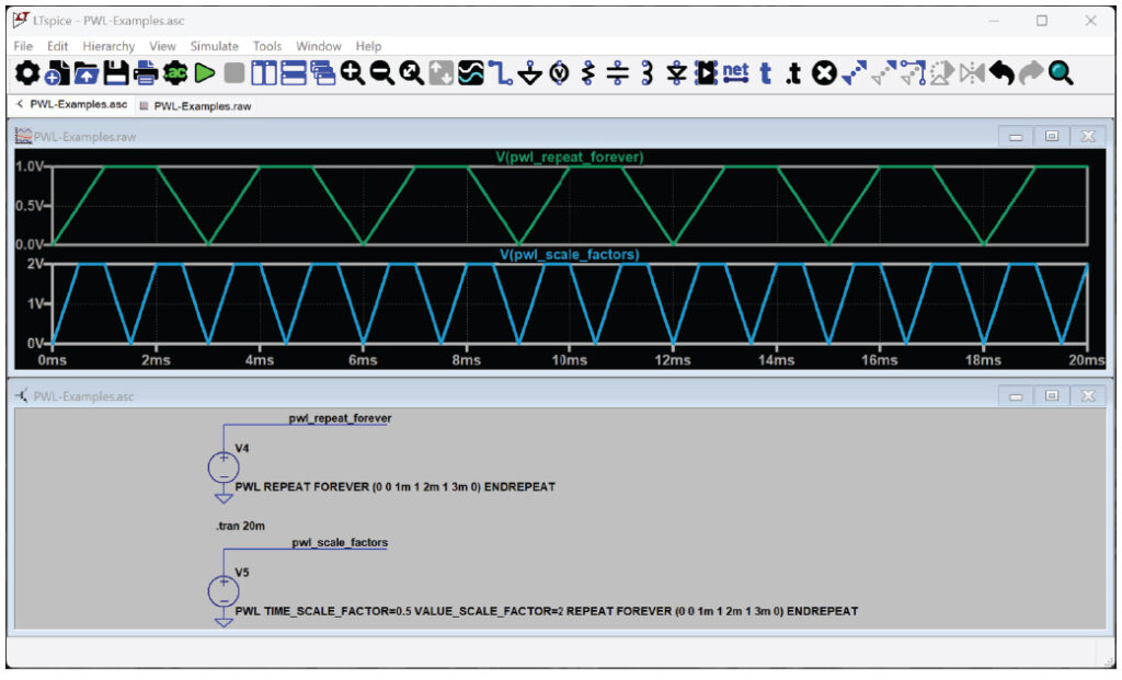
PWL parameters TIME_SCALE_FACTOR and VALUE_SCALE_ FACTOR can be used to stretch or shrink the waveform. Figure 6 shows the original waveform with half the period length and twice the amplitude:
PWL TIME_SCALE_FACTOR=0.5 VALUE_SCALE_FACTOR=2 REPEAT FOREVER (0 0 1m 1 2m 1 3m 0) ENDREPEAT

Defining a PWL Waveform with a Text File
To build waveforms with a large number of points, importing those points from a text file will help to keep the schematic less cluttered. The file name is specified in the PWL statement:
PWL REPEAT FOREVER FILE=data.txt ENDREPEAT
Figure 7 shows the text file and resulting waveform using an example of an imported waveform that repeats indefinitely. See the LTspice manual for more information about importing waveform data, including FILE, SCOPEDATA, and WAVEFILE import syntax.
PWL functions are documented in the Voltage Source and Current Source sections of the LTspice manual for further study.
Conclusion
When transient simulations require an arbitrary source waveform, PWL functions provide flexibility to define (or import) waveform data.
About the Author
Anne Mahaffey joined Analog Devices in 2003 as a test engineer supporting direct digital synthesis products after receiving her B.S.E.E. from the Georgia Institute of Technology and her M.S.E.E. from North Carolina State University. She spent over 10 years architecting and supporting design tools in the Precision Studio tool suite and now supports LTspice® as a principal applications engineer.